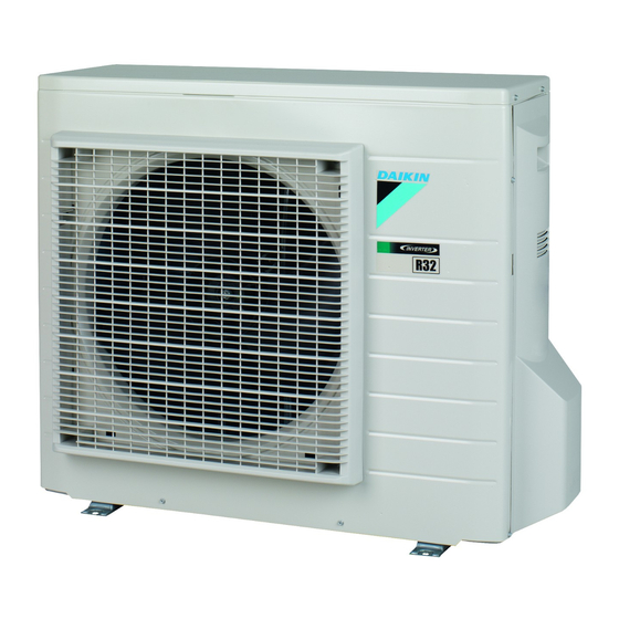
Daikin RXF50A2V1B Installation Manual

Daikin RXF50A2V1B Installation Manual

R32 split series

Advertisement

Installation manual

R32 split series
Installation manual
RXF50A2V1B
English
R32 split series
RXF60A2V1B

Advertisement

Table of Contents
loading

Summary of Contents for Daikin RXF50A2V1B

  • Page 1: Installation Manual

    Installation manual R32 split series Installation manual RXF50A2V1B English R32 split series RXF60A2V1B...
  • Page 2 3P511700-6A...
  • Page 3 2P427092-13L...
  • Page 4 2P427092-13L...
  • Page 5 ▪ A subset of the latest technical data is available on the regional 4.4.2 To perform vacuum drying .......... 10 Daikin website (publicly accessible). Charging refrigerant ..............10 ▪ The full set of latest technical data is available on the Daikin 4.5.1 About charging refrigerant .......... 10 extranet (authentication required). 4.5.2 About the refrigerant ...........
  • Page 6: To Remove The Accessories From The Outdoor Unit

    3 Preparation Preparation Preparing the installation site CAUTION ▪ Check if the installation location can support the unit's weight. Poor installation is hazardous. It can also cause vibrations or unusual operating noise. ▪ Provide sufficient service space. ▪ Do NOT install the unit so that it is in contact with a ceiling or a wall, as this may cause vibrations.
  • Page 7: Mounting The Outdoor Unit

    4 Installation Gas piping Ø12.7 mm (1/2") ▪ Piping temper grade and thickness: Outer diameter Temper grade Thickness (t) (Ø) Ø Annealed (O) 6.4 mm (1/4") ≥0.8 mm 12.7 mm (1/2") Depending on the applicable legislation and the unit's maximum working pressure (see "PS High" on the unit name plate), larger piping thickness might be required.
  • Page 8 4 Installation (mm) In any case, provide at least 300  mm of free space below the unit. Additionally, make sure the unit is positioned at least 100 mm above (mm) the maximum expected level of snow. In this case, it is recommended to construct a pedestal.
  • Page 9: Connecting The Refrigerant Piping

    4 Installation 4.2.2 To install the outdoor unit 4× M8/M10 4.2.3 To provide drainage NOTICE If the unit is installed in a cold climate, take adequate measures so that the evacuated condensate CANNOT freeze. Connecting the refrigerant piping INFORMATION For information on the available options, contact your DANGER: RISK OF BURNING dealer.
  • Page 10: Charging Refrigerant

    4 Installation 5 If you do NOT reach the target vacuum or CANNOT maintain 4.3.3 To connect the refrigerant piping to the the vacuum for 1 hour, do the following: outdoor unit ▪ Check for leaks again. ▪ Piping length. Keep field piping as short as possible. ▪...
  • Page 11: About The Refrigerant

    4 Installation 4.5.2 About the refrigerant 4.5.4 To determine the complete recharge amount This product contains fluorinated greenhouse gases. Do NOT vent gases into the atmosphere. INFORMATION Refrigerant type: R32 If a complete recharge is necessary, the total refrigerant charge is: the factory refrigerant charge (see unit name Global warming potential (GWP) value: 675 plate) + the determined additional amount.
  • Page 12: Guidelines When Connecting The Electrical Wiring

    5 Commissioning WARNING If the supply cord is damaged, it MUST be replaced by the manufacturer, its service agent or similarly qualified persons in order to avoid a hazard. WARNING Do NOT connect the power supply to the indoor unit. This could result in electrical shock or fire.
  • Page 13: Checklist During Commissioning

    6 Disposal The indoor unit is properly mounted. Starting up the outdoor unit See the indoor unit installation manual for configuration and The outdoor unit is properly mounted. commissioning of the system. The system is properly earthed and the earth terminals are tightened.
  • Page 14: To Start And Stop Forced Cooling

    6 Disposal Gas stop valve Closing direction Hexagonal wrench Valve lid Liquid stop valve To start and stop forced cooling There are 2 methods to perform forced cooling operation: ▪ using the indoor unit ON/OFF switch (if present on the indoor unit).
  • Page 15: Wiring Diagram

    7 Technical data Technical data A subset of the latest technical data is available on the regional Daikin website (publicly accessible). The full set of latest technical data is available on the Daikin extranet (authentication required). Wiring diagram Unified Wiring Diagram Legend For applied parts and numbering refer to the wiring diagram sticker supplied on the unit.
  • Page 16: Piping Diagram

    7 Technical data Piping diagram Piping diagram: Outdoor unit RXF60A2V1B 7.2.1 PED categories of equipment - High pressure switches: category IV; Compressor: category II; Other art. 4§3 equipment. Note: When the high pressure switch is activated it must be reset manually by a qualified person. Installation manual RXF50+60A2V1B R32 split series...
  • Page 20 3P512025-3 2017.11...

This manual is also suitable for:

Rxf60a2v1b

Table of Contents