Table of Contents
Advertisement
Advertisement
Table of Contents

Subscribe to Our Youtube Channel
Related Manuals for Advantech DS-780


Summary of Contents for Advantech DS-780
- Page 1 User Manual DS-780 Multi-Display Digital Signage Player with Fanless Design...
- Page 2 No part of this manual may be reproduced, copied, translated or transmitted in any form or by any means without the prior written permission of Advantech Co., Ltd. Information provided in this manual is intended to be accurate and reliable. How- ever, Advantech Co., Ltd.
- Page 3 Because of Advantech’s high quality-control standards and rigorous testing, most of our customers never need to use our repair service. If an Advantech product is defec- tive, it will be repaired or replaced at no charge during the warranty period. For out- of-warranty repairs, you will be billed according to the cost of replacement materials, service time and freight.
- Page 4 Increase the separation between the equipment and receiver. Connect the equipment into an outlet on a circuit different from that to which the receiver is connected. Consult the dealer or an experienced radio/TV technician for assistance. DS-780 User Manual...
-
Page 5: Packing List
Packing List Before installation, please ensure the following items have been shipped: 1 x DS-780 Unit 1 x accessory box including: – 1 x Power Adaptor – 1 x Bracket set for fixing power adapter plug – 2 x Mounting Brackets –... -
Page 6: Safety Instructions
Remplacer uniquement avec un modèle recommandé par le fabricant, et éliminer les piles usagées selon les instructions du fabricant. DISCLAIMER: This set of instructions is given according to IEC 60950-1(ed.2). Advantech disclaims all responsibility for the accuracy of any statements contained herein. DS-780 User Manual... - Page 7 Display ..................2 1.2.3 Power Consumption..............2 Hardware Specifications ................3 Mechanical Specifications................. 4 1.4.1 Dimensions ................... 4 Figure 1.1 DS-780 mechanical dimensions ......... 4 1.4.2 Weight................... 4 Power Requirements................. 4 1.5.1 System Power................4 1.5.2 RTC Battery .................. 4 Environment Specification.................
- Page 8 2.4.2 HDD/SSD Installation ..............15 Figure 2.13HDD/SSD installation ..........15 2.4.3 Mini PCIe card / M.2 / SIM Card and Antenna Installation ..16 Figure 2.14Mini PCIe / M.2 / SIM card installation ..... 16 Figure 2.15Antenna module installation ........17 2.4.4 Mount Brackets Installation............
-
Page 9: Chapter 1 General Introduction
Chapter General Introduction This chapter gives background information of DS-780 series. -
Page 10: Introduction
Digital signage is one of the most effective and eye-catching communications medi- ums on the market. Advantech DS-780 is an ideal digital signage player. It’s not only a high graphic performance computer but also a low power for advanced Digital Sig- nage Player. -
Page 11: Hardware Specifications
Processor Graphics: Intel® IRIS Graphics 540 (i7-6650U / i5-6360U), Intel® HD Graphics 520 (i7-6600U/i5-6300U/i3-6100U), Intel® HD Graphics 510 (Cel- eron-3955U) Storage: Supports 1 x 2.5" SATA HDD/SSD Watchdog Timer: Supported by Advantech SUSIAccess API I/O Interface: – COM: 1 x RS-232 –... -
Page 12: Mechanical Specifications
37.25 1.47 206 [8.110] 7 [0.276] 14.50 [0.571] 11.25 0.44 2.05 74.50 2.93 Figure 1.1 DS-780 mechanical dimensions 1.4.2 Weight 1.5 kg (3.3 lb) Power Requirements 1.5.1 System Power Minimum power input: DC 19V, 3.42A 1.5.2 RTC Battery 3V/220 mAh CR2032... -
Page 13: Environment Specification
1.0 Grms, IEC 60068-2-64, random, 5 ~ 500 Hz , 3 axes,1 hr/axis. 1.6.5 Shock During Operation 10 G, IEC 60068-2-27, half sine, 11 ms duration 1.6.6 Safety UL,CB, BSMI, CCC 1.6.7 CE/FCC Class B, BSMI, CCC DS-780 User Manual... - Page 14 DS-780 User Manual...
-
Page 15: Chapter 2 Hardware Installation
Chapter Hardware Installation This chapter describes DS-780 external I/O and explains the hard- ware installation processes. -
Page 16: Ds-780 Front And Rear Views
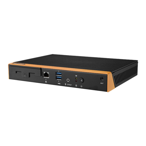
DS-780 Front and Rear Views SPDIF/ Line out/ 2.5” Storage Bracket LAN2 USB3.0 x 2 PWR Button Mic in Status LED WIFI/HDD Figure 2.1 Front view 19V DC-in HDMI x 3 USB3.0 x 2 LAN1 Figure 2.2 Rear view DS-780 User Manual... -
Page 17: Ds-780 Front External I/O Connectors
DS-780 Front External I/O Connectors 2.2.1 Power ON/OFF Button DS-780 has a power ON/OFF button on front side. Push this button to turn the sys- tem ON and OFF. It can also support 4 second delay soft power off. Figure 2.3 Power button 2.2.2... -
Page 18: Ethernet Connector (Lan)
2.2.4 Ethernet Connector (LAN) DS-780 provides two RJ45 LAN interface connectors (1 x LAN in front-side; 1 x LAN in rear-side), they are fully compliant with IEEE 802.3u 10/100/1000 Base-T stan- dards. The Ethernet port provides a standard RJ-45 jack connector with LED indica- tors on the front side to show its Active/Link status and speed status. -
Page 19: Hdmi Connector
2.3.3 USB Connectors DS-780 rear side provides 2 x USB3.0 interface connectors, which give complete Plug & Play and hot swapping capability for up to 127 external devices. The USB 3.0 is compliant with USB UHCI, Rev. 3.0. (Pin definition refer Table 2.1) Figure 2.9 USB 3.0 connector... -
Page 20: Com Connector
2.3.4 COM Connector DS-780 provides 1 x D-sub 9-pin connectors serial communication interface port. The port can support RS-232 mode communication. Figure 2.10 COM connector Table 2.4: COM Port Pin Assignments Signal Name DS-780 User Manual... -
Page 21: Hardware Installation
Loosening the 4 fixing screws on the side of top cover. Remove the top cover. Insert the memory module into memory socket Assemble back the heatsink cover with the 4 screws MEMORY Figure 2.11 Memory module installation-Top side DS-780 User Manual... -
Page 22: Figure 2.12Memory Module Installation-Bottom Side
Loosening the 1 fixing screw on the memory cover in bottom side. Remove the memory cover. Insert the memory module into memory socket Assemble back the memory cover with the 1 screw. MEMORY Figure 2.12 Memory module installation-bottom side DS-780 User Manual... -
Page 23: Hdd/Ssd Installation
HDD/SSD Installation Loosening the screw on the front view and move out the drive bay. Fixing the 4 screws with HDD/SSD and storage bracket. Insert the storage bracket into chassis Fixing the screw back. Figure 2.13 HDD/SSD installation DS-780 User Manual... -
Page 24: Mini Pcie Card / M.2 / Sim Card And Antenna Installation
Assemble the antenna cable to mini PCIe/ M.2 module on the bottom side. Assemble back the mini PCIe cover with the screw. Assemble back the top cover with the screws Mini pcie Figure 2.14 Mini PCIe / M.2 / SIM card installation DS-780 User Manual... -
Page 25: Figure 2.15Antenna Module Installation
Figure 2.15 Antenna module installation DS-780 User Manual... -
Page 26: Mount Brackets Installation
2.4.4 Mount Brackets Installation Loosening the fixing screws on the bottom side. Fixing the two mount brackets with 4 screws directly. Figure 2.16 Mount brackets installation DS-780 User Manual... -
Page 27: Rubber Feet Installation
2.4.5 Rubber Feet Installation Retrieve the four rubber feet from the accessory box. Attach the rubber feet to the four corners and fixing them by four screws directly. Figure 2.17 Rubber feet Installation DS-780 User Manual... - Page 28 DS-780 User Manual...
-
Page 29: Chapter 3 Bios Settings
Chapter BIOS Settings This chapter introduces how to set BIOS configuration data. -
Page 30: Bios Introduction
Using the AMI BIOS Setup program, users can modify the BIOS settings and control various system features. This chapter describes the basic navigation of the BIOS setup screens for the DS-780 series. The AMI BIOS’s ROM features a built-in setup program that allows users to modify the basic system configuration. -
Page 31: Advanced Bios Setup
3.2.2 Advanced BIOS Setup Select the Advanced tab from the DS-780 setup screen to enter the Advanced BIOS setup screen. You can select any of the items in the left frame of the screen, such as CPU configuration, to go to the sub menu for that item. You can display an Advanced BIOS Setup option by highlighting it using the <Arrow>... -
Page 32: Figure 3.3 Acpi Setup Screen
This item allows users to control hardware monitoring and power management. Figure 3.3 ACPI setup screen AMT Configuration This section is used to configure Active Management Technology (AMT) options. Intel® AMT Enables or disables Active Management Technology DS-780 User Manual... - Page 33 PCH-FW Configuration Configure Management Engine Technology Parameters ITE8528E Super I/O Configuration System super I/O chip parameters DS-780 User Manual...
- Page 34 ITE8528E HW Monitor Enabled or disabled watch dog timer function (Start before boot to OS and must by self) S5 RTC Wake Settings Enable or disable system wake on alarm event. DS-780 User Manual...
- Page 35 Serial Port Console Redirection Console redirection enable or disable CPU Configuration CPU configuration parameters DS-780 User Manual...
- Page 36 Intel TXT Information SATA Configuration Enable or disable SATA Device DS-780 User Manual...
- Page 37 Network Stack configuration Enable/Disable UEFI network stack. CSM Configuration Enable/disable option ROM execution DS-780 User Manual...
- Page 38 1, 5, 10, and 20 seconds. – Device Reset Timeout Allows users to set the USB mass storage device start unit command timeout time; options include 10, 20, 30, and 40 seconds. – Device Power-Up Delay Enable/disable DS-780 User Manual...
-
Page 39: Bios Chipset Setup
3.2.3 BIOS Chipset setup Select the Chipset tab in the DS-780 BIOS Setup Utility to enter the BIOS Chipset setup screen. Users can select any item displayed in the left frame of the screen. Figure 3.4 BIOS Chipset setup ... - Page 40 Wake on WLAN Enable from DeepSx Enable/Disable PCI Express wireless LAN to wake the system from DeepSx. – State after G3 Specify what state to go to when power is re-applied after a power failure (S3 state) DS-780 User Manual...
-
Page 41: Bios Security Setup
3.2.4 BIOS Security setup Select the Security tab from the setup screen to enter the BIOS Security setup screen. Set Administrator Password and User password. Figure 3.5 BIOS Security setup DS-780 User Manual... -
Page 42: Bios Boot Setup
3.2.5 BIOS Boot setup Select the Boot tab from the DS-780 setup screen to enter the BIOS Boot setup screen. Users can select any item in the left frame of the screen. Figure 3.6 BIOS Boot setup Setup Prompt Timeout Allows users to set the number of seconds to wait for a setup activation key. -
Page 43: Bios Save& Exit Setup
Restore User Defaults Restore the User Defaults to all setup options Boot Override – Launch EFI Shell From File System Device Allows users to launch the EFI Shell application (Shell.efi) from an available file system device DS-780 User Manual... - Page 44 No part of this publication may be reproduced in any form or by any means, electronic, photocopying, recording or otherwise, without prior written permis- sion of the publisher. All brand and product names are trademarks or registered trademarks of their respective companies. © Advantech Co., Ltd. 2016...
Need help?
Do you have a question about the DS-780 and is the answer not in the manual?
Questions and answers