Table of Contents
Advertisement
Quick Links
Consultation with SebaKMT
User Manual
Noise Level and Frequency Logger
Sebalog N3
Mess- und Ortungstechnik
Measuring and Locating Technologies
Elektrizitätsnetze
Power Networks
Kommunikationsnetze
Communication Networks
Rohrleitungsnetze
Water Networks
Abwassernetze
Sewer Systems
Leitungsortung
Line Locating
1
1 (08/2011) - ENG
Advertisement
Table of Contents

Subscribe to Our Youtube Channel
Related Manuals for sebaKMT Sebalog N3


Summary of Contents for sebaKMT Sebalog N3
- Page 1 Consultation with SebaKMT User Manual Noise Level and Frequency Logger Sebalog N3 Mess- und Ortungstechnik Measuring and Locating Technologies Elektrizitätsnetze Power Networks Kommunikationsnetze Communication Networks Rohrleitungsnetze Water Networks Abwassernetze Sewer Systems Leitungsortung Line Locating 1 (08/2011) - ENG...
- Page 2 Consultation with SebaKMT...
-
Page 3: Consultation With Sebakmt
© SebaKMT All rights reserved. No part of this handbook may be copied by photographic or other means unless SebaKMT have before-hand declared their consent in writing. The content of this handbook is subject to change without notice. SebaKMT cannot be made liable for technical or printing errors or shortcomings of this handbook. -
Page 4: Terms Of Warranty
This warranty does not apply to faults in the software supplied. During the period of warranty, SebaKMT agree to repair faulty parts or replace them with new parts or parts as new (with the same usability and life as new parts) according to their choice. - Page 5 Contents Contents Consultation with SebaKMT ................... 3 Terms of Warranty ......................4 Contents ........................... 5 Technical description ..................7 Technical data ....................9 Scope of delivery and accessories ..............12 Optional accessories ..................12 Important and common terms ..............13 The loggers .....................
- Page 6 Contents 5.1.3 Defining a workgroup ..................32 Programming the loggers ................. 33 Installing the loggers ..................35 Reading out the measured data ............... 37 5.4.1 Reading out a “Lift&Shift” group ............... 38 5.4.2 Reading out a “Patrol” group ................39 Evaluating the measured data .................
-
Page 7: Technical Description
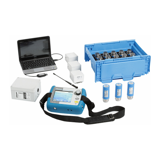
Technical description Technical description Function Sebalog N-3 is a system for acoustically monitoring pipe systems. It has Log N-3 noise level loggers and the Commander-3 as its basis. The Commander is used for programming the loggers as well as reading out and analysing the recorded measurements. - Page 8 Technical description Components The Sebalog N-3 system consists of the following components: Component Log N-3 measures regularly the volume level and frequency of the noise in noise loggers the pipe during the programmed measuring window. Commander-3 is the portable device for programming the loggers before measuring, and for reading out and analysing the recorded data after measuring.
-
Page 9: Technical Data
Technical description Technical data Logger The noise level loggers in the Sebalog N-3 system are specified by the following technical parameters: Parameter Value Wireless interface (bidirectional) Frequency 868 MHz (915 MHz optional) • Transmitting power 10 mW • Range Approx. 80 m (depends on the surroundings) •... - Page 10 Technical description Reader-3 The Reader-3 reading device in the Sebalog N-3 system is specified by the following technical parameters: Parameter Value Display LCD display (b/w), 128 x 32 pixels Wireless interface (bidirectional) Frequency 868 MHz (915 MHz optional) • Transmitting power 10 mW •...
- Page 11 Technical description GSM box-3 The GSM box in the Sebalog N-3 system is specified by the following technical parameters: Parameter Value Wireless interface (bidirectional) Frequency 868 MHz (915 MHz optional) • Transmitting power 10 mW • Range Max. 400 m (depends on the surroundings) •...
-
Page 12: Scope Of Delivery And Accessories
Technical description Scope of delivery and accessories The Sebalog N-3 system is delivered with the following as standard: Logger set A logger set consists of the following components: Designation Description Item No.: LOG N-3 Noise level logger 820019682 (number depending on set size) LOG TB-240 Transport box 118303892... -
Page 13: Important And Common Terms
Important and common terms Important and common terms User mode The Commander-3 can be operated in two different user modes (see page 23): Easy mode • Professional mode • You can switch between these modes in system settings menu (see page 25). Level and frequency These two values are identified each time a noise logger performs a measurement: …... - Page 14 Important and common terms Workgroup The Commander can only ever interact with a single registered logger group. This group is called the “workgroup”. It is not possible to program or read loggers from another group. Measuring window The “measuring window” is the time during which a logger is programmed to carry out measurements, e.g.
-
Page 15: The Loggers
The loggers The loggers Function The noise loggers are installed along a section of pipe directly on the pipe, or directly on fittings on the pipe. Within the configured measuring window, they perform regular noise measurements, each 3 seconds in length. The volume level and frequency of each measurement are saved in the logger. -
Page 16: Design
The loggers Design Introduction All noise loggers have a highly sensitive microphone with a large dynamic range, a data memory and a lithium battery inside. The standard loggers also have an internal radio antenna. Standard version The loggers have the following external characteristics: “Head”... -
Page 17: Switching On And Off
Severe fluctuations in climatic conditions also have a negative impact. Flat batteries cannot be recharged. They must be replaced. SebaKMT or an authorised service partner must change the batteries. Otherwise, water- and dirt-resistance of the logger cannot be guaranteed. -
Page 18: The Commander
The Commander The Commander Function The Sebalog Commander 3 is the mobile programming and reading device for noise loggers in the Sebalog N-3 series. The Commander is used to program the noise loggers before measuring. After measuring, the recorded data in the loggers can be queried with the Commander. -
Page 19: Device Design
The Commander Device design Controls and The Commander has the following controls and connections: connections Element Description Selector knob ESC button I/O button Device on/off • Backlight on/off • Charging indicator light Lights up red … external supply, battery is being charged •... -
Page 20: Design Of The User Interface
The Commander Design of the user interface All the menu levels on the Commander’s user interface consist of a large display area and an infobar on the bottom edge of the screen. The content and structure of the display area change depending on the system status. Display area Main menu bar (Professional mode... -
Page 21: Basics Of Operation
The Commander Basics of operation Navigation within the The Commander is very simple to operate and intuitive in principle. Navigation within the menus menus is done exclusively with the aid of the selector knob as follows: Turning select open/confirm Pressing (ENTER function) The selected element appears on a black background: Selected... - Page 22 The Commander Virtual keyboard To input comments or similar, a virtual keyboard appears on the screen, which is also operated with the selector knob. … deletes last character … switches between upper- and lower-case … inserts space … confirms and completes input Sorting loggers Various menus list the individual loggers of a logger group.
-
Page 23: User Mode
The Commander User mode Introduction The Commander-3 can be operated in two different user modes. Easy mode Professional mode In Easy mode all the main functions of the In Professional mode all the functions of device are available. They can perform the device are available to the user. -
Page 24: Making A Connection
The Commander Making a connection 4.6.1 Connection between the Commander and logger Short range radio is used for communication between the Commander and loggers. The Commander has an integrated radio module. After the antenna is connected (standard or vehicle antenna), the device is ready for wireless operation. The loggers must be switched on and wirelessly available (see page 52). -
Page 25: Switching On The Display Lighting
The Commander Switching on the display lighting The Commander’s screen has a backlight. It is activated by using the selector knob or briefly pressing the I/O button . The lighting then remains on for a certain time period. The length of this period (a maximum of 4 minutes) can be adjusted in the system settings (see page 26). -
Page 26: Basic Settings
The Commander 4.8.1 Basic settings The following basic settings can be made in both Professional mode and Easy mode: Line Description User mode Select a user mode for the device (see page 26). Language Select a language for the user interface. If you cannot read the preset language, you can go to the language selection - starting from the main menu - via the following symbols:... -
Page 27: Extended Settings In Professional Mode
The Commander 4.8.2 Extended settings in Professional mode The following extended settings are only available in Professional mode: Line Description Logger list visibility Select table columns to be shown/hidden. Various menu levels list the loggers of a group in a table on the screen. -
Page 28: System Info
The Commander 4.8.3 System info When the Commander is operated in Professional mode, the System settings menu has the following information on the device and the firmware currently in use: Line Description Free space Commander’s free memory space in MB Software version Firmware version of the Commander Software date/time... -
Page 29: Updating The Firmware
(at least one bar on the battery symbol on the infobar (see page 20)). If in doubt, recharge the battery first (see page 30). Download the latest firmware archive from www.sebakmt.com and extract it to a directory on your PC. -
Page 30: Memory
CAUTION If you experience problems with the battery, please contact your SebaKMT sales partner. Do not open the device yourself. The stated water- and dirt- resistance can only be guaranteed if any work on the device is performed solely by service departments authorised to do so. -
Page 31: Working In Easy Mode
Working in Easy mode Working in Easy mode Starting up the Commander 5.1.1 Switching on the Commander Switch on the Commander by pressing the I/O button The Easy mode main menu appears on the screen: Name of the System date workgroup Changing the In Easy mode, the... -
Page 32: Defining A Workgroup
Working in Easy mode 5.1.3 Defining a workgroup More than one group of loggers can be registered in the Commander. However, the Commander can only work with one of these groups at a time. This group is called the “workgroup”. Specify the workgroup for the impending measurement session. -
Page 33: Programming The Loggers
Working in Easy mode Programming the loggers Introduction The loggers in the workgroup must be reprogrammed before each session. This means that the Commander sends basic data for the session wirelessly to the loggers (e.g. the measuring window). Procedure To program the workgroup proceed as follows: Step Description In the main menu, select the Prepare loggers... - Page 34 Working in Easy mode Step Description Switch on all the loggers in the group, i.e. place them “on their foot”. Select the OK button to confirm. Result: The next display provides information about the data used to program the loggers. (It is not possible to change this configuration data in Easy mode).
-
Page 35: Installing The Loggers
Working in Easy mode Installing the loggers Basics Install the loggers of the workgroup in succession along the stretch of pipe. It is best to fit them directly on the pipe. However, you can also attach the loggers to valve rods or hydrants, for example, or any other position along the pipeline that is easily accessible. - Page 36 Working in Easy mode Installation examples The following pictures show a few methods for installing N-3 noise loggers: Logger on the valve rod of an Logger on an underground hydrant underground hydrant Logger with an angle adapter Logger with an angle adapter on the valve rod on the hydrant claw Logger with an angle adapter...
-
Page 37: Reading Out The Measured Data
Working in Easy mode Reading out the measured data After the loggers have been installed on location for at least one measuring day, the recorded measured data can be read out with the Commander. The exact same group mode (“Lift&Shift”/“Patrol”/”Network”) for which the workgroup was programmed is used. Groups with an “L”... -
Page 38: Reading Out A "Lift&Shift" Group
Working in Easy mode 5.4.1 Reading out a “Lift&Shift” group To read out the measured data in the loggers, proceed as follows: Step Description Collect up all the loggers of the group and place them next to the Commander. Avoid placing the loggers on their head! The stored data would not be lost if the loggers were switched off, but it would no longer be indicated if a logger is in leak status or not (see page 14). -
Page 39: Reading Out A "Patrol" Group
Working in Easy mode 5.4.2 Reading out a “Patrol” group To read out the measured data in the loggers, proceed as follows: Step Description In the main menu of the Commander, select the Patrol Loggers button. Result: The Commander is ready to receive the measured data from the individual loggers. - Page 40 Working in Easy mode Step Description The detected logger switches from the right-hand to the left-hand window on the Commander screen. The coloured background of the read data reflects the probability of a leak. No colour … Leak probability low, leak threshold was not exceeded Grey …...
-
Page 41: Evaluating The Measured Data
Working in Easy mode Evaluating the measured data You can use the Commander to view the measured data read out from a logger and to analyse it in greater detail. 5.5.1 Calling up the measured values To call up the measured data of a logger, proceed as follows: Step Description In the main menu, select the Display logger data... -
Page 42: Displaying The Measured Values
Working in Easy mode 5.5.2 Displaying the measured values View The measured data from the loggers are shown as a bar diagram on the screen. Element Description Identification number and comment of the displayed logger Diagram Each bar represents a single noise recording. X-axis ... - Page 43 Working in Easy mode Functions There are the following functions for analyzing the displayed data: Button Description Scroll You can use this function to view in the diagram the measurement results of the other loggers in the group. To do so, apply the button and turn the selector knob to select a logger. Apply the button again to confirm your selection.
-
Page 44: Working In Professional Mode
Working in Professional mode Working in Professional mode Starting up the Commander 6.1.1 Switching on the Commander Switching on Use the I/O button to switch on the Commander. The Professional mode start image appears on the screen: Workgroup Firmware version, Main menu bar System date, Identification number of... -
Page 45: Managing The Loggers
Working in Professional mode Managing the loggers All loggers to be used for a measurement must be registered in the Commander beforehand. Only registered loggers can be programmed and read. Registration is performed either by manually inputting the logger ID or by automatic wireless detection. The registered loggers are combined in groups. - Page 46 Working in Professional mode Renaming a group You can rename an existing logger group. First select the particular group in the list and then select the Rename button. In the following screen views, enter a group mode (see page 13) and the new name of the group.
-
Page 47: Managing The Loggers In The Commander
Working in Professional mode 6.2.2 Managing the loggers in the Commander Select the symbol in the main menu, and the Logger Management button in the next view, to go to the menu for managing loggers. The loggers of the workgroup (see page 45) are listed. - Page 48 Working in Professional mode Registering loggers A logger can be registered manually by entering its ID. Proceed as follows: manually Step Description Apply the Add logger button. Type in the logger’s six-digit ID using the displayed keyboard (see page 14). Confirm the input with the ENTER button.
- Page 49 Working in Professional mode Deleting loggers You can delete a logger from the displayed group. Proceed as follows: Step Description Select the logger in the list. Apply the Delete button and answer the confirmation query with Yes. Result: The logger is no longer contained in the list. If the logger is not contained in any other existing group, it is simultaneously de- registered from the Commander.
-
Page 50: Programming The Loggers
Working in Professional mode Programming the loggers Introduction Each logger must be configured before each measuring session. They are assigned with all the relevant parameters before the impending measurement. Even loggers that have already been programmed and installed can usually be reprogrammed. - Page 51 Working in Professional mode Measuring parameters The following parameters must be stated in order to define the measuring window: Parameter Description Measurement Beginning and end of the daily measuring window. (from … to) Select from: 0:00 to 24:00 hours Default: 2 a.m. to 4 a.m. Explanation: The logger performs measurements and saves the measurement values within the stated window.
- Page 52 Working in Professional mode Radio parameters Continuous wireless availability and frequent wireless exchange of data have a detrimental effect on the lifetime of a logger’s battery. To spare the battery, the periods of wireless availability and activity can be restricted. To do this, the following parameters must be entered: Parameter Description...
-
Page 53: Installing The Loggers
Working in Professional mode Continuing Proceed as follows to continue the programming process: programming Step Description Enter the data in turn for the group or the single logger. Apply the Program button in order to finish the programming. Result: The configuration data is Result: The configuration data is transferred from the Commander to the transferred from the Commander to the... -
Page 54: Reading Out The Measured Data
Working in Professional mode Reading out the measured data After a group has been installed for at least one measuring day, the recorded data can be called up with the Commander. The same group mode for which the workgroup was configured is used (see page 13). Furthermore, you can always read just a single logger instead of a group. -
Page 55: Standard Query Of A Single Logger
Working in Professional mode 6.5.2 Standard query of a single logger If you only wish to read a single logger with the commander, proceed as follows: Step Description Select the symbol in the main menu bar. In the next menu, select the Read measurement data button. Result: The loggers in the workgroup are listed in the next view. -
Page 56: Evaluating The Measured Data
Working in Professional mode Evaluating the measured data 6.6.1 Calling up the measured values Calling up recent To view the measured values from a logger on the Commander’s screen, select the measured data symbol in the main menu and then the Display logger data button. The loggers in the workgroup are listed in the next view: If necessary, you can call up a different group using the drop-down list at the very top of the screen. -
Page 57: Displaying The Measured Values
Working in Professional mode 6.6.2 Displaying the measured values Introduction In Professional mode the measured data from the loggers is shown as a bar diagram on the screen just as in Easy mode (see page 42). But, additionally the Professional mode provides the opportunity to compare the measured data of two loggers. -
Page 58: Additional Measuring Functions
Additional measuring functions Additional measuring functions Real time measurement Introduction The “Real time measurement” function allows you to follow, in real time, the current noise level and the frequency in a pipe directly on location and without additional measuring devices. A logger measures continuously and immediately transfers the data to the Commander. - Page 59 Additional measuring functions Display of The course of the real time measurement is shown on the Commander’s screen with a measured data running bar diagram: Element Description Identification number and comment of the observed logger Diagram Each bar represents a single noise recording. X-axis ...
-
Page 60: Audio Recordings
Additional measuring functions Audio recordings Loggers in the Sebalog N-3 series are able to save recorded noises as audio files and to send them to the reading device. This means the user is no longer reliant on the measurement values alone (level/frequency/ESA value) when evaluating a noise. You can actually listen to the suspected leak. -
Page 61: Playing Back The Audio Data
Additional measuring functions 7.2.2 Playing back the audio data Introduction After an audio file is sent from a logger to the Commander, it can be played back with the Commander and listed to over headphones. First, connect the supplied headphones to the Commander via the 5-pin headphone socket . -
Page 62: Displaying The Frequency Spectrum Of The Leak Noise (In Professional Mode Only)
Additional measuring functions 7.2.3 Displaying the frequency spectrum of the leak noise (in Professional mode only) Introduction In Professional mode, you can view the frequency spectrum of the saved leak noise for an even more in-depth analysis. Purpose Sometimes the assumed leak noise stems from a known source of interference (e.g. 50 Hz/100 Hz mains voltage or a pump in operation). -
Page 63: Recording A Noise Directly (In Professional Mode Only)
Additional measuring functions 7.2.4 Recording a noise directly (in Professional mode only) Introduction The “Direct recording” function of a Log N-3 logger enables you to listen in on the current noise in a pipe without using additional equipment (sensor rod microphone or similar). -
Page 64: Increasing The Wireless Range Of The Loggers With Repeaters When Patrolling (In Professional Mode Only)
Increasing the wireless range of the loggers with repeaters when patrolling (in Professional mode only) Increasing the wireless range of the loggers with repeaters when patrolling (in Professional mode only) Introduction The actual wireless range of a noise logger depends on the conditions at the place of use. -
Page 65: Repeater Design
When you query a repeater’s configuration, its battery status is also shown. Flat batteries cannot be recharged. They must be replaced. SebaKMT or an authorised service partner must change the batteries. Otherwise, water- and dirt-resistance of the repeater cannot be guaranteed. -
Page 66: Installing The Wireless Extension
Increasing the wireless range of the loggers with repeaters when patrolling (in Professional mode only) Installing the wireless extension Before the wireless extension via repeaters can be set up, the logger concerned must already be programmed and installed at its place of use. Proceed on location as follows: Step Description... - Page 67 Increasing the wireless range of the loggers with repeaters when patrolling (in Professional mode only) Step Description Apply the Start button. The logger and repeater are connected. The vertical blue line in the bar indicator shows the strength currently of the wireless connection between the logger and repeater.
Need help?
Do you have a question about the Sebalog N3 and is the answer not in the manual?
Questions and answers