Table of Contents
Advertisement
Quick Links
Advertisement
Table of Contents

Subscribe to Our Youtube Channel
Related Manuals for sebaKMT Sebalog D


Summary of Contents for sebaKMT Sebalog D
- Page 1 Operating Instructions Alarm IN Data Logger Sebalog D Mess- und Ortungstechnik Measuring and Locating Technologies Elektrizitätsnetze Power Networks Kommunikationsnetze Communication Networks Rohrleitungsnetze Water Networks Leitungsortung Line Locating Issue: 1 (09/2008)
- Page 3 © SebaKMT All rights reserved. No part of this handbook may be copied by photographic or other means unless SebaKMT have before-hand declared their consent in writing. The content of this handbook is subject to change without notice. SebaKMT cannot be made liable for technical or printing errors or shortcomings of this handbook.
- Page 4 SebaKMT. All warranty claims versus SebaKMT are hereby limited to a period of 12 months from the date of delivery. Each component supplied by SebaKMT within the context of warranty will also be covered by this warranty for the remaining period of time but for 90 days at least.
-
Page 5: Table Of Contents
Contents Safety Advices........................1-7 Technical Description...................... 2-8 Technical Data ........................2-8 Scope of Delivery ......................... 2-9 Available Configurations....................... 2-9 Design ..........................2-11 Accessories ........................2-13 Commissioning the Logger................... 3-14 Configuring the Logger....................... 3-14 Preparing the Logger for GSM Connectivity............... 3-14 Connecting the Logger ....................... - Page 6 5.2.1.1 Configuring a „Customer Specific“ Sensor ................. 5-37 5.2.1.2 Input Type Examples ......................5-38 5.2.2 Configuring Alarm Conditions (Threshold Monitoring)..........5-40 5.2.3 Finishing the Configuration..................5-41 Configuring the Switching Inputs (Alarm Inputs)..............5-42 Configuring the Radio Communication ................5-44 5.4.1 SIM Card Configuration ....................
-
Page 7: Safety Advices
Safety Advices Safety precautions This manual contains basic advice for the installation and operation of the Sebalog D. It is essential to make this manual accessible to the authorized and skilled operator. He needs to read this manual closely. The manufacturer is not liable for damage to material or humans due to non-observance of the instructions and safety advices provided by this manual. -
Page 8: Technical Description
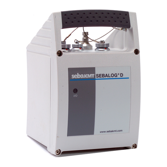
Technical Description Intended application The Sebalog D is a compact, robust and extremely versatile data logger. The device can record the readings of various sensor types in user-defined intervals. The collected data can be periodically transmitted to a FTP server or read out with a PC or special equipment. -
Page 9: Scope Of Delivery
Scope of Delivery Besides of the logger unit and a magnet, the Sebalog D package contains a CD with the following content: • SebaDataView configuration and readout software • Driver • Sebalog D information materials Depending on the configuration of the logger, the scope of delivery may contain even more accessories which can also be ordered from SebaKMT (see section 2.5). - Page 10 4-channel versions Item number Type Item number Type 820012348 LOG D4-B 820012354 LOG D4-I-B 820012349 LOG D4-P1-16 820012355 LOG D4-I-P1-16 820013478 LOG D4-P1-25 820013487 LOG D4-I-P1-25 820013479 LOG D4-P1-40 820013488 LOG D4-I-P1-40 820012350 LOG D4-P2-16 820012356 LOG D4-I-P2-16 820013480 LOG D4-P2-25 820013489 LOG D4-I-P2-25 820013481...
-
Page 11: Design
Design Controls and indicators The following figure shows all the front panel operating controls and indicators. The unit is in protection class IP 68: The Sebalog D consists of the following operating controls and indicators: Item Description On/off contact area... - Page 12 Connectors The following figure shows the connectors of the Sebalog D which are placed on top of the device. While the USB socket is always part of the assembly, it depends on the configuration of the logger whether the other connectors are existent:...
-
Page 13: Accessories
Accessories In addition to the standard scope of delivery, there is a large amount of optional accessory parts which can be ordered from SebaKMT. The following table describes all available accessory parts: Accessory part Description Item number Connection cable - for connecting the logger to up to 4... -
Page 14: Commissioning The Logger
Commissioning the Logger Configuring the Logger Prior to its on-site installation, the logger must be properly configured using the supplied SebaDataView software. In doing so, the logger has to be provided with the channel allocation, the alarm conditions and the wireless connection parameters among other things. - Page 15 A new front panel can be ordered from SebaKMT. • The rubber seal and the contact surfaces of the housing must be free of dirt.
-
Page 16: Connecting The Logger
Depending on the type of sensors / alarm devices connected to the Sebalog D, the appropriate parameter values have to be provided to the logger using the SebaDataView software. - Page 17 Fixed channel allocations Due to the internal wiring of the logger, current loops can only be connected to the channels 2 and 4. The internal pressure sensors P1 and P2 are always linked to channel 1 and 3. If the logger is equipped with one or two internal pressure sensors, the respective channels are in use and must not be connected to external sensors.
-
Page 18: Connection Equipment For Single-Channel Loggers
3.3.1.2 Connection Equipment for Single-channel Loggers Introduction Loggers with only one channel (LOG D-1) can be connected to one sensor, a switching input and a switching output. All of these connections can be established with only one connection cable (VK 76) attached to the USB / DC ext. socket VK 76 pin assignment in In combination with a single-channel logger, the VK 76 connection cable has the combination with... -
Page 19: Connection Equipment For Multi-Channel Loggers
3.3.1.3 Connection Equipment for Multi-channel Loggers Introduction Multi-channel loggers are equipped with the additional IN socket up to 4 external sensors can be connected to (via the VK 75 connection cable). The switching inputs/outputs and the external power supply have to be connected to the USB / DC ext. - Page 20 VK 76 pin assignment in In combination with a multi-channel logger, the VK 76 connection cable has the combination with multi- following pin assignment: channel loggers (to be connected to USB / DC ext.) Wire Description white Switching An alarm-triggering device with a voltage output of Input 1 0 …...
-
Page 21: Wiring Diagram Examples
3.3.1.4 Wiring Diagram Examples Introduction The examples described in the following pages can be realized with any type of logger even with the basic version with only one channel. For multi-channel loggers, these examples can be combined in many ways depending on the logger configuration. - Page 22 Connecting a sensor with The following examples describe how to connect a sensor with a 0 Hz … 1000 Hz the output signal type frequency output. frequency Example 1: the logger does not supply the operating voltage for the sensor: Sensor Logger 5 V OUT...
- Page 23 Connecting a sensor with The following examples describe how to connect a sensor with pulse output. These the output signal type types of sensors transmit a pulse to the logger whenever the value of the measurement crosses a certain threshold. pulse (reed contact) Example 1: the logger does not supply the operating voltage for the sensor: Logger...
- Page 24 Example of an alarm loop The following example shows an electrical circuit with DC power source connected to the switching input of the loggers. If an alarm is raised by the alarm device (e.g. light barrier) is activated, the circuit is closed and the switching input is triggered. Depending on the alarm configuration, one or two of the internal relays are switched in order to activate / trigger the load connected to the respective switching output (in this case a signal lamp) and a SMS and / or email can be sent to predefined...
-
Page 25: Connecting A Tube To An Internal Pressure Sensor
3.3.2 Connecting a Tube to an Internal Pressure Sensor A Sebalog D logger can be equipped with up to two internal pressure sensors (optional 10 bar, 16 bar, 25 bar or 40 bar) where tubes can be connected to. The sensors are capable of measuring the pressure of both liquid and gaseous media. -
Page 26: Commissioning The Logger
Commissioning the Logger 3.4.1 Positioning the Logger Thanks to its IP68 protection class, the logger housing is protected against the ingress of dust and water and, thus, especially qualified for the operation in pipeline shafts where it can be installed next to the measuring point. The logger can be installed in vertical and horizontal position and can also be hung up using, e.g., a cable tie. -
Page 27: Switching The Logger On/Off
Switching the Logger On/Off The logger is switched on by moving the supplied magnet in front of the contact area . After the magnet switch has been activated, the I/O control lamp is lit green for a moment and starts flashing green after the logger has been started up. The device is now in energy saving mode. -
Page 28: Setting Up The Software
Setting Up the Software The Sebalog D does not dispose of a display or any controls. Any communication (configuration, data readout) with the device is performed using the SebaDataView software. System Requirements Your machine must meet the following minimum system requirements in order to run the SebaDataView software: •... -
Page 29: Connecting The Logger To The Pc
Connecting the Logger to the PC If you would like to configure a logger or to retrieve data from a logger, a connection to the logger has to be established first. This connection can be either established via the VK 77 USB cable or via radio communication using the E-Box. 4.3.1 Radio Communication via E-Box Introduction... -
Page 30: Connecting The Logger Via Direct Connection
(C:\ Program Files \SebaKMT\SebaDataView\USBDriver) where the driver has been automatically stored during software installation. Windows may report that the driver is not certified and warn for possible danger. Since the driver is not causing any danger for your system you can continue the installation. -
Page 31: Starting The Software
Starting the Software Start the application by double-clicking on the desktop icon created during the installation process. Alternatively, the application can be started via the Windows start menu. During start-up you are asked to select the language of the user interface. Make your choice and click on OK. -
Page 32: Registering A Logger
Registering a Logger In order to configure or read out a logger, the device has to be added to the database, if this has not been done before. All loggers which have been added to the database are shown in the logger tree on the left side of the screen. 4.5.1 Adding / Deleting a Logger Adding a logger... -
Page 33: Adding / Deleting A Group
Deleting a logger Perform the following steps in order to remove a logger from the database: Step Action Select the logger to be deleted in the logger tree. Proceed in one of the following ways: Select Logger -> Delete from the menu bar. Right-click on the logger in the logger tree and select Delete from the context menu. - Page 34 Deleting a group Perform the following steps in order to remove a group from the logger tree: Step Action Select the group to be deleted in the logger tree. If a group is deleted, all loggers assigned to this group and its sub- groups are deleted too and the collected data is lost.
-
Page 35: Configuring The Logger
Configuring the Logger Introduction Before a logger can be installed in the field, the device has to be properly configured. In doing so, you can specify the inputs / outputs, the logging intervals, the alarm conditions and the radio communication settings, among other things. Preparation Proceed as follows to access the configuration of a specific logger: Step... -
Page 36: Selecting The Logging Interval
Selecting the Logging Interval You can select the time interval in which the measured values are logged from the Logging interval drop-down list. Sensor Configuration Introduction Depending on its configuration, up to 4 sensors can be connected to a logger. In order to evaluate the logged data in the right way, the logger needs to know which type of sensor is connected to which channel. -
Page 37: Sensor Type
The internal pressure sensors (Seba Standard Pressure) of the Sebalog D are also part of this list. The measuring range of the internal pressure senor can be obtained from the type number of the logger (see section 2.3). -
Page 38: Input Type Examples
5.2.1.2 Input Type Examples Input type Voltage A 10 bar pressure sensor with voltage output is connected to a channel of the logger. Input type: Voltage 0-5V Unit: The lower limit of the measuring range (0 bar) is indicated by a voltage value of 0 V while the upper limit (10 bar) correlates with 5 V. - Page 39 A flowmeter with a digital pulse output is connected to a channel of the logger. The Input type Pulse flowmeter transmits one pulse per 16 litre. input type: Pulse Unit: The flow can be measured per hour or per second. If per hour is selected, the logging interval must be higher than 15 minutes.
-
Page 40: Configuring Alarm Conditions (Threshold Monitoring)
5.2.2 Configuring Alarm Conditions (Threshold Monitoring) Introduction The Sebalog D can trigger an alarm whenever a specified minimum or maximum threshold is crossed. That way, up to two connected devices (e.g. a pump or a valve) can be triggered by the internal relays. -
Page 41: Finishing The Configuration
When a maximum threshold is exceeded, the device connected to the internal relay is switched on. The device is switched off as soon as the measured value falls below the threshold again. This applies for the lower threshold the other way around. A relay cannot be assigned to more than one alarm. -
Page 42: Configuring The Switching Inputs (Alarm Inputs)
Configuring the Switching Inputs (Alarm Inputs) Introduction Depending on its configuration a logger can be equipped with up to two switching inputs (alarm inputs) which can be connected to active circuits. For each of these inputs, it can be specified which input voltage value causes an alarm. An example of such an alarm loop is shown in section 3.3.1.4. - Page 43 Configuring an After an alarm input has been activated, it must be specified which input voltage alarm input value causes an alarm and which actions are triggered by an alarm. Click the respective Configuration button. The following window appears: Proceed as follows to configure an alarm input: Step Action Specify the input voltage value which does, when present at the...
-
Page 44: Configuring The Radio Communication
Configuring the Radio Communication Configuring a timeframe Data transfer between logger and PC can be performed via radio connection using for radio communication the E-Box (see section 4.3.1). If radio communication is going to be established during a specific timeframe only (e.g. during daytime), the range of this timeframe has to be specified via the Radio on from and Radio is off from fields. - Page 45 Further information can be obtained from the website or the hotline of the mobile network operator. If necessary, request guidance for setting up data communication in particular. SebaKMT cannot provide any specific technical advice in this case. Proceed as follows to set up data communication via GPRS:...
-
Page 46: Sim Card Configuration
Username and password can be specified during the account setup procedure or can be requested from your system administrator. SebaKMT does not provide email accounts. Enter a sender email address into the Name field. This address should clearly... -
Page 47: Ftp Settings
5.4.4 FTP Settings If you want the logged data to be transferred to a FTP server at regular intervals, you have to specify the server settings. You can ask your administrator to set up a FTP server using the server infrastructure of your company or you can rent a server from an ISP. -
Page 48: Testing The Gsm Settings
5.4.7 Testing the GSM Settings You can send a test email or a test SMS in order to check whether a GSM connection can be established with the active settings. Furthermore, the FTP settings can be tested by creating a file to the respective FTP folder. The GSM configuration must have been already finished (see previous sections) and the settings must have been transferred to the logger before a test can be performed (see section 5.8). - Page 49 (Continuation from previous page:) Step Action If no SMS or email has been received, the logger probably failed to establish a GSM connection. Click on the Read GSM log button in order to identify possible sources of the problem. A message of the following layout appears in the display area: GSM LOG: Date and time of the test...
-
Page 50: Testing Ftp Data Transfer
5.4.7.2 Testing FTP Data Transfer Perform the following steps to check the FTP settings: Step Action Click on the Test GSM settings button. Result: A new window appears. Click on the Send Test FTP data button. Thereupon, the logger tries to create a test file inside the respective folder on the FTP server. -
Page 51: Memory Mode
Memory Mode The logger has 2 MB internal memory. By default, the device stops logging as soon as the memory is full. By checking the Ring memory checkbox, the logger can be set to ‘ring buffer’ mode. As the memory fills up with data in this mode, the device keeps logging and the respective oldest value is overwritten. -
Page 52: Retrieving And Evaluating Data
Retrieving and Evaluating Data Retrieving Data from the Logger The data can be readout via cable connection (see section 4.3.2) or radio link (see section 4.3.1). Proceed as follows, to readout the data from the logger: Step Action Make sure, the logger is connected to your PC (either via USB cable or via E-Box). -
Page 53: Collecting Data From The Ftp Server
Collecting Data from the FTP Server If the logger is equipped with a GSM modem, the logged data can be automatically transmitted to a FTP server (see section 5.4.4). You can access a FTP server from any PC with an internet connection. Proceed as follows to download the data from the FTP server: Step Action... -
Page 54: Evaluating Measured Data
Evaluating Measured Data Displaying the After the measured data has been retrieved from the logger (see section 6.1), the measured data progression of the measured values can be illustrated in a diagram and, by this means, can be easily evaluated. Proceed as follows to display the data of a specific logger: Step Action... - Page 55 Navigating through the You can use the navigation panel at the lower right of the window to navigate: measured values Arrow keys Scrolling along the axes Magnifier Zooming in and out In addition you can use the mouse wheel for navigation (you have to click on the diagram first): Mouse wheel Scrolling along the X-axis...
-
Page 56: Miscellaneous Functions
Miscellaneous Functions Identifying Loggers This function can be used to identify all loggers within the radio range of the E-Box (see also section 4.3.1). The function can be also used to identify a logger connected via USB interface. Proceed in one of the following ways to access this function: Select Logger ->... -
Page 57: Setting The Clock
Setting the Clock In order to make the measurement results comparable over time, the loggers must be time-synchronous. For this purpose, the internal clock of all loggers within the radio range of the E-Box can be adjusted to the system time. This also works if only one logger is connected to the PC via USB interface. -
Page 58: Firmware
Result: The current firmware version is displayed. Updating the firmware Please check our website www.sebakmt.com frequently for an updated Sebalog D firmware version. If a newer version is available, save the file to your hard disk and proceed as follows to update the firmware of the logger:... -
Page 59: Replacing The Batteries
Replacing the Batteries Introduction The internal lithium batteries of the Sebalog D are able to supply a constant voltage level over a long period. Under ideal conditions, a logger can be operated for up to five years without changing the batteries. The voltage level can be read off from the Voltage parameter in the logger configuration window (see section 5.7).
Need help?
Do you have a question about the Sebalog D and is the answer not in the manual?
Questions and answers