Table of Contents
Advertisement
Advertisement
Table of Contents

Subscribe to Our Youtube Channel
Related Manuals for Physio Control lucas 2


Summary of Contents for Physio Control lucas 2
-
Page 1: Instructions For Use
INSTRUCTIONS FOR USE 100901-00 Rev B, Valid from CO J3166 © 2017 Jolife AB... - Page 2 Thank you for choosing the LUCAS 2 Chest Compression System! With LUCAS 2 your cardiac arrest patients will receive effective, consistent and continuous chest compressions as reommended in the American Heart Association guidelines. If you have any questions about this product or its operation, please contact your local Physio-Control representative or the manufacturer JOLIFE AB.
- Page 3 Table of Contents Important user information ........5 Introduction .
- Page 4 Replace the Power Supply during operation ......21 5.7.1 Change the Battery ........... 21 5.7.2 Connect to the external Power Supply .
-
Page 5: Important User Information
1 Important user information The information in these Instructions for Use applies to the LUCAS™2 Chest Compression System, also referred to as LUCAS. All operators must read the complete Instructions for Use before operating the LUCAS Chest Compression System. The Instructions for Use must always be easily accessible to the operators of LUCAS. -
Page 6: Introduction
2 Introduction 2.1 LUCAS™ Chest Compression 2.4 Side effects System The International Liaison Committee on The LUCAS™ Chest Compression System is Resuscitation (ILCOR) states these side a portable tool designed to overcome effects of CPR problems identified with manual chest "Rib fractures and other injuries are common compressions. -
Page 7: Lucas™ Components
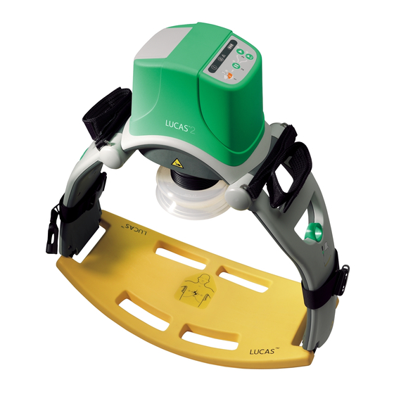
™ 2.6 LUCAS components 1. User Control Panel LUCAS Stabilization Strap* 2. Hood 20. Cushion strap 3. Patient Strap* 21. Buckle 4. Release ring 22. Support leg strap 5. Support leg 6. Claw locks 7. Back Plate* 8. DC input 9. -
Page 8: User Control Panel
2.7 User Control Panel MUTE: If you push this key when LUCAS operates, you mute the alarm for 60 seconds. If you push this key when LUCAS is powered OFF, the Battery indicator shows the Battery charge status of the Battery. Battery indicator: The three green LEDs show the Battery charge status:... -
Page 9: Safety Precautions
3 Safety precautions 3.3 Contraindications Do NOT use the LUCAS Chest Compression System in these cases: To ensure maximum safety, always read this section carefully before operating, carrying • If it is not possible to position LUCAS safe- out any work on the equipment or making ly or correctly on the patient's chest. -
Page 10: Symbols On The Device
3.5 Symbols on the device Symbols on type label S S ymbol Meaning Caution – keep your fingers away Do not put your hands on or below the Symbols on type label Suction Cup when LUCAS operates. Keep your fingers away from the claw Symbol Meaning locks when attaching the Upper Part Follow instructions for use... -
Page 11: General Safety Precautions
3.6 General safety precautions 3.8 Operation Caution - use only approved accessories WARNING - UNSATISFACTORY Use only JOLIFE AB-approved accessories POSITION Start manual CPR again if it is not possible to with LUCAS. LUCAS may not operate position LUCAS safely and correctly on the correctly if you use accessories that are not patient's chest. -
Page 12: Service
3.9 Service WARNING - ECG interference Chest compressions interfere with ECG We recommend a yearly servicing of LUCAS analysis. Push PAUSE before you start the to make sure that it operates correctly. Use ECG analysis. Make the interruption as short the original shipping box when you send as possible. -
Page 13: First Use Preparations
4 First use preparations 4.2.1 Charge the Battery You can charge the LUCAS Battery in two ways: 4.1 Delivered items LUCAS™2 Chest Compression System is • In the external LUCAS Battery Charger supplied in one box with: (optional) • A LUCAS device (Upper Part and Back - put the Battery in the slot of the Plate) Battery Charger,... -
Page 14: Prepare The Lucas™ Stabilization Strap
4.3 Prepare the LUCAS™ 4.4 Prepare the Carrying Bag Stabilization Strap Before the first use of LUCAS, attach the support leg straps, which is a part of the Stabilization Strap, to the LUCAS support legs. 1. Fold one support leg strap around each LUCAS support leg. -
Page 15: Arrival At The Patient
5 Use LUCAS™ 3. Push ON/OFF on the User Control Panel for 1 second to power up LUCAS in the bag and start the self test. The green LED adjacent to the ADJUST key illumi- 5.1 Arrival at the patient nates when LUCAS is ready for use. -
Page 16: Apply To Patient
5.3 Apply to patient 5. Start manual CPR again. 6. Hold the handles on the support legs to 1. Remove the LUCAS Back Plate from the remove the LUCAS Upper Part from the Carrying Bag. bag. Pull the release rings once to make sure that the claw locks are open. -
Page 17: Adjustment And Operation
8. Attach the support leg that is nearest to 5.4 Adjustment and operation you to the Back Plate. The compression point should be at the same spot as for manual CPR and according to guidelines. When the pressure pad in the Suction Cup is in the correct position, the lower edge of the Suction Cup is immediately above the end of the sternum. - Page 18 1. Use your finger to make sure that the c. Push PAUSE to lock the Start Position lower edge of the Suction Cup is imme- - then remove your fingers from the diately above the end of the sternum Suction Cup. If necessary, move the device by pulling the support legs to adjust the position.
-
Page 19: Apply The Lucas™ Stabilization Strap
WARNING - INCORRECT START Caution - do not block the vent holes Do not cause a blockage of the vent holes POSITION under the hood since this can cause the The patient's blood circulation is device to become too hot. compromised if the pressure pad presses down too heavily or too lightly on the chest. -
Page 20: Move The Patient
6. Make sure that the position of the Suc- 5.6.2 Prepare to lift the patient tion Cup is correct on the patient's 1. Make a decision about what equipment chest. you will move and where to put the trans- portation device. If it is not, adjust the position: 2. -
Page 21: Move The Patient
5.6.4 Move the patient 5.7.1 Change the Battery LUCAS can be active while you move the Keep interruptions to a minimum while patient if: changing the Battery. • LUCAS and the patient are safely posi- Note: To minimize interruptions, we tioned on the transportation device recommend to always have a charged spare LUCAS Battery in the Carrying Bag. -
Page 22: Connect To The External Power Supply
5.7.2 Connect to the external Power 5.8.1 Defibrillation Supply Defibrillation can be performed while LUCAS operates. You can connect the LUCAS Power Supply or Car Power Cable in all LUCAS operating modes. 1. You can apply the defibrillation elec- trodes before or after LUCAS has been Caution - keep Battery installed put in position. -
Page 23: Ventilation
6 Care after use and 5.8.2 Ventilation Always follow local and/or international preparation for next use guidelines for ventilation. LUCAS can operate in two different modes: Do the following after each use of the LUCAS Chest Compression System: • ACTIVE (continuous) 1. -
Page 24: Cleaning Routines
6.1 Cleaning routines 6.3 Remove and attach the Patient Straps Clean all surfaces and straps with a soft cloth and warm water with a mild cleaning agent Remove: or disinfectant agent, e.g. 1. Open the Patient Straps and pull them •... -
Page 25: Remove And Attach The Lucas™ Stabilization Strap
6.4 Remove and attach the Caution - use only approved accessories Use only JOLIFE AB-approved accessories ™ LUCAS Stabilization Strap with LUCAS. LUCAS does not operate correctly if you use accessories that are not Remove the Support leg straps, which is a approved. -
Page 26: Troubleshooting
8 Troubleshooting 8.1 Indications and alerts during normal operation Refer to the table below to find the reason for sound and/or LED alarms during normal operation. Situation Visual LED indication Audible signals User action LUCAS is in the ON mode and Fully charged Bat- None None... -
Page 27: Battery Replacement And Smart Restart Feature
Situation Visual LED indication Audible signals User action In the ACTIVE (continuous) mode The ACTIVE (continu- None This is to alert for ous) key, LUCAS per- ventilation during forms continuous ongoing com- chest compressions. pressions. The green LED signal will blink 8 times per minute In the ACTIVE (30:2) mode The ACTIVE (30:2) -
Page 28: Malfunction Alarms
8.3 Malfunction alarms Below is a list of all alarms that can occur on LUCAS. You mute all alarms for 60 seconds if you push MUTE. Start with manual compressions immediately if LUCAS does not operate properly. Priority Reason Visual LED indication Audible alarms Result Rising temperature in... -
Page 29: Technical Specifications
9 Technical specifications All specifications in this chapter apply to the LUCAS™2 Chest Compression System. 9.1 Patient parameters Category Specifications Patients eligible for treatment: Adult patients who fit into the device; • sternum height of 6.7 to 11.9 inches / 170 to 303 •... -
Page 30: Battery Physical Specifications
9.5 Battery physical specifications Category Specifications Size (H × W × D) 5.1 x 3.5 x 2.2 inches / 13.0 × 8.8 × 5.7 cm Weight 1.3 lbs / 0.6 kg Type Rechargeable Lithium Ion Polymer (LiPo) Capacity 3300 mAh (typical), 86 Wh Battery voltage (nominal) 25.9 V Initial Battery runtime (nominal patient) -
Page 31: Audible Signals
9.8 Audible SIGNALS 9.8.1 Audible ALARM SIGNALS, characteristics Audible Sequence of tones Durations Tone Sound Situations System Result signal +/- 5ms frequency level delays name +/- 10 Hz (dB@1m) +/-0.5s +/- 5dB High = 200ms Self-test error 1 to 10s Inoperable = 530 Hz priority... -
Page 32: Audible Information Signals, Characteristics
9.8.2 Audible INFORMATION SIGNALS, characteristics Audible Sequence of tones Durations Tone Sound Description Situation signal +/- 5ms frequency level name +/- 10 Hz (dB@1m) +/- 5dB Power ON = 375ms = 1 kHz Continues until self- Self-test during signal = 0ms test is complete Power ON of the device... -
Page 33: Electromagnetic Environmental Declaration
NOTE UT is the a.c. mains voltage prior to application of the test level. Guidance and manufacturer's declaration - electromagnetic immunity LUCAS 2 is intended for use in the electromagnetic environment specified below. The customer or the operator of LUCAS 2 must make sure that it is used in the correct environment. - Page 34 To assess the electromagnetic environment due to fixed RF transmitters, an electromagnetic site survey should be considered. If the measured field strength in the location in which LUCAS 2 is used exceeds the applicable RF compliance level above, LUCAS 2 should be observed to make sure it operates normally. If unusual or incorrect performance is observed, additional measures can be necessary, such as reorienting or relocating LUCAS 2.
- Page 35 Rated maximum output Separation distance according to frequency of transmitter power of transmitter 150 kHz to 80 MHz 80 MHz to 800 MHz 800 MHz to 2.5 GHz 1.2 P 1.2 P 1.3 P 0.01 0.12 0.12 0.24 0.38 0.38 0.73 For transmitters rated at a maximum output power not listed above, the recommended separation distance d in meters (m) can be estimated using the equation applicable to the frequency of the transmitter, where P is the maximum output power...
-
Page 36: Limited Warranty
9.10 Limited warranty Subject to the limitations and exclusions set forth below, JOLIFE AB ("JOLIFE") warrants that JOLIFE products which are purchased from authorized JOLIFE representatives or dealers and are used in accordance with their instructions will be free from defects in material and workmanship appearing under normal service and use for the time period listed below. - Page 37 150201-00 LUCAS Stabilization Strap 150203-00 LUCAS Patient Straps 150204-00 LUCAS 2 Power Supply, MWB100024A, Art. Nr: 300 000-00 (regional versions) 150210-XX LUCAS 2 Power Supply, MWA150028B, Art. Nr: 300 000-00 (regional versions) 150214-XX LUCAS 2 Car Power Cable 12-28VDC 150206-00...
- Page 38 LUCAS 2 Chest Compression System – Instructions for Use 100901-00 Rev B, Valid from CO J3166 © 2017 Jolife AB 100901-00 Rev A, Valid from CO J2716 © 2014 Jolife AB...
- Page 39 LUCAS 2 Chest Compression System – Instructions for Use 100901-00 Rev B, Valid from CO J3166 © 2017 Jolife AB 100901-00 Rev A, Valid from CO J2716 © 2014 Jolife AB...
- Page 40 QUICK REFERENCE GUIDE NOTE: This guide is not a complete Instructions for Use. Refer to the “Instructions for Use” for complete directions for use, indications, contraindications, warnings, precautions, and potential adverse events. ON/OFF ADJUST PAUSE ACTIVE ACTIVE (continuous) (30:2) Confirm cardiac arrest and start manual CPR with a minimum of interruptions until LUCAS is applied and ready.
Need help?
Do you have a question about the lucas 2 and is the answer not in the manual?
Questions and answers