Essence Care Home User Manual
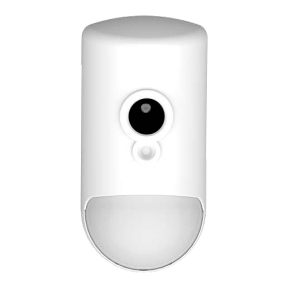
Camera detector
Hide thumbs
Also See for Care Home:
- User manual (30 pages) ,
- Getting started (4 pages) ,
- User manual (20 pages)
Advertisement
Advertisement
Table of Contents

Related Manuals for Essence Care Home


Summary of Contents for Essence Care Home
- Page 1 Care@Home™ Camera Detector User Guide ESUGSC006 Version 2.0 July 2017...
- Page 2 Table of Contents Table of Contents Overview ..............................3 Installing the IPD ............................ 4 2.1. Determining the Best Location ....................4 2.1.1 Basic Location Requirements ..................4 2.1.2 Locations to Avoid ....................... 6 2.2. Checking if a Pet Immune Lens is Required................8 2.3.
-
Page 3: Overview
Overview 1. Overview The Essence Camera Detector (IPD) is a battery operated, bi-directional, wireless device combining the functionality of a passive infrared (PIR) motion detector with a high-resolution, full-color, JPEG- image-capturing camera. Figure 1: Essence Camera Detector Care@Home™ Camera Detector User Guide... -
Page 4: Installing The Ipd
Installing the IPD 2. Installing the IPD To install the IPD: Ensure you have three 1.5 V AA alkaline batteries NOTE: To comply with the UL certification standards, use GP International Ltd. batteries. Determine the best location Check if a pet immune lens is required ... - Page 5 Installing the IPD A surface that is clean, dry, and smooth At a height of 2 to 2.2 m (6.6 to 7.2 ft.) Within 400 m (1,312 ft.) of the control panel (CP) NOTE: The IPD has a maximum detection range of 12 m (40 ft.), and maximum detection angles of 105°...
-
Page 6: Locations To Avoid
Installing the IPD 2.1.2 Locations to Avoid The mounting location should not be: On a door frame. Where objects obscure the coverage area, even partially. For example, bookcases or cabinets. A location that has moving objects in the coverage area. - Page 7 Installing the IPD Directly in front of an air conditioner or heat source. Directly opposite a door. For example, if the IPD is installed facing the door, when the resident passes the open door through the hallway, the IPD sends an event to the CP reporting incorrectly that the resident is entering the bathroom.
-
Page 8: Checking If A Pet Immune Lens Is Required
Installing the IPD 2.2. Checking if a Pet Immune Lens is Required If there are pets on the premises, it is important to differentiate between the movement of the resident and the movement of the pet by using a pet immune lens. Instructions for fitting a pet immune lens are included in 2.3 Setting Up the IPD on page 8. - Page 9 Installing the IPD NOTE: Refer to Using Screws on page 22, for information about installing the IPD using screws. 4. Peel off the protective strips from the mounting tape required for the installation location. For installing in a corner For installing on a flat wall Figure 4: Peel Off the Protective Strips 5.
- Page 10 Installing the IPD 6. Remove the battery cover, by pressing the tab and pushing the cover up and out. Figure 6: Remove the Battery Cover 7. If the IPD does not require a pet immune lens, skip ahead to step 16 on page 14. 8.
- Page 11 Installing the IPD Figure 8: Detach Back Cover Caution: Be careful not to damage the internal parts of the IPD. 10. Use a flat screwdriver to release the three latch tabs on the front panel so that the outer lens falls free from the IPD.
- Page 12 Installing the IPD 11. Insert the pet immune lens into the opening for the lens in the IPD front panel. The pet immune lens fits inside the opening of the IPD. Figure 10 Insert Pet Immune Lens into the IPD 12.
- Page 13 Installing the IPD 13. Insert the tabs, at the bottom end of the front panel, into the inner square slots, at the bottom end of the back cover. Figure 12: Align and Insert Tabs in Square Slots 14. Put the back cover into the front panel. Figure 13: Put the Back Cover into the Front Panel 15.
- Page 14 Installing the IPD 16. On the CP, press the PAIRING button for five seconds. PAIRING button Figure 15: Press the CP PAIRING Button 17. Move the IPD at least 2 m (~6 ft. 7 in.) from the CP. 18. Shake the IPD gently. The rattling sound is the tamper-prevention mechanism. 19.
-
Page 15: Conducting A Walk Test
Installing the IPD 20. Ensure that the pairing process is successful. The process can have the following results: The CP beeps and the CP ring blinks blue three times. Success The CP beeps and the CP ring lights up red for two seconds. Try to pair the Failure IPD again. - Page 16 Installing the IPD The Walk Test mode starts automatically after the IPD powers up, such as: When a new battery is inserted After adding and pairing a new IPD with the Care@Home ™ system This mode lasts 10 minutes. During the Walk Test, you can check the detection area of the IPD by walking past it at different points.
-
Page 17: Operating The Ipd
Operating the IPD 3. Operating the IPD The IPD monitors activity and reports it by sending notifications to the CP. The IPD also takes video. 3.1. Notifications The IPD sends notifications to the CP for the following events: A motion detection event ... -
Page 18: Replacing The Battery
Replacing the Battery 4. Replacing the Battery The battery status is reported automatically to the monitoring station via the CP. When the status indicates that the battery charge is low, the battery must be replaced. Discard used batteries responsibly. WARNING! A new battery can cause damage if it is incorrectly installed. - Page 19 Replacing the Battery 2. Remove the battery cover by pressing the tab and pushing the cover up and out. Figure 19: Remove the Battery Cover 3. Remove the old batteries. 4. Shake the IPD gently. The rattling sound is the tamper-prevention mechanism. 5.
-
Page 20: Specifications
Specifications 5. Specifications The following table lists all the technical aspects and data about the IPD. Table 1: Device Technical Specifications Category Details Essence Part number ES700IPD Image Capture Resolution VGA, QVGA, QQVGA Illumination for night and Auto-activated bright white LED... - Page 21 Specifications Category Details Encoding 32-bit ID, over 4 billion combinations Functional Main MCU Advanced false alarm suppression algorithms Advanced gain temperature control Immunity Sealed PCB Multiple detection mechanism Minimum time between detections: 2.5 minutes Walk test Automatic after power-up, 10 minutes Visual indications LED for detection, tampering, and walk test RFI protection...
-
Page 22: Using Mounting Tape
Installation Method Alternatives Installation Method Alternatives Appendix A There are two ways to install the IPD mounting base: Using mounting tape Using screws Before choosing the installation method, consider the following: Installation with mounting tape is more common. ... -
Page 23: Required Equipment
Installation Method Alternatives At an angle facing to the right or the left In a corner Required Equipment Before beginning, prepare the following equipment: A drill with a standard bit 3 X 35 DIN 7982 C screws and wall anchors: ... - Page 24 Installation Method Alternatives Screw Holes The following figures show the screw holes to use for each type of installation. The corner support holes are blocked by the mounting tape. You can drill through the tape. Figure 20: Holes for Figure 21: Holes for Installing in Installing on a Flat Wall a Corner Figure 22: Holes for...
- Page 25 Nothing contained herein shall be construed as conferring by implication, estoppels, or otherwise any license or right, either express or implied, under any patent or trademark of Essence or any third party. No use of any trademark may be made without the prior written authorization of Essence.
Need help?
Do you have a question about the Care Home and is the answer not in the manual?
Questions and answers