Table of Contents
Advertisement
Advertisement
Table of Contents

Related Manuals for DSC GS3060-RF


Summary of Contents for DSC GS3060-RF
-
Page 1: Installation Manual
GS3060-RF GSM-GPRS INTERFACE INSTALLATION MANUAL WARNING: This manual contains information on limitations regarding product use and function and information on the limitations as to liability of the manu- facturer. The entire manual should be carefully read. - Page 3 Connecting the GS3060-RF ........
-
Page 4: Fcc Compliance Statement
DSC c/o APL Logistics, 757 Douglas Hill Rd., Lithia Springs, GA 30122 may cause interference to radio and television reception. It has been type... -
Page 5: Introduction
Mechanical Specifications Dimensions (enclosure GS3060-RF): ..130mm × 350mm × 107.5mm / 5.1” × 13.78” × 4.2” Weight (without battery): ....... 1433g / 3.16lbs Simulated Telco Loop specifications (TIP/RING) On-Hook Voltage: . -
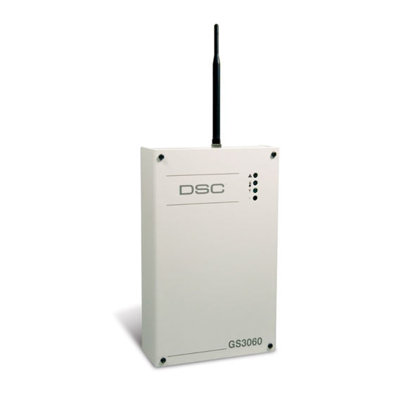
Page 6: Identification Of Parts
Figure 1 - Parts LOCK OPEN OFF ON NOTE: For UL/ULC installa- tions, connections between the alarm control panel out- puts (telephone interface Tip/Ring, output relay con- tacts) GS3060-RF inputs (Tip/Ring, Z1-Z4) TAMPER + DC IN - PGM1 PGM2 PGM3 PGM4... -
Page 7: Description
Description This GS3060-RF manages transmissions to a central station and can simulate the landline in the event of trouble (e.g., landline down) or even substitute the landline completely in areas where the GSM service is provided and a landline is not available. -
Page 8: Connecting The Gs3060-Rf
JP3 OFF - Current limiting mode, the host panel or external supply provides standby current. Supply must be capable of 120mA plus any current drawn from AUX+ terminal. GS3060-RF battery must be installed for proper operation. Use only with supplied power supply. -
Page 9: Status Leds
GSM network. This feature is only active when the GS3060-RF is configured as a back up communicator. This feature is in addition to the regular line voltage detection. -
Page 10: Gprs Sequence
The GS3060-RF has four open collector outputs capable of a maximum of 50mA. Internal events on the GS3060-RF can trigger the outputs to turn on an LED or activate an input on the host panel. The default settings are as follows. -
Page 11: Contact Id
NOTE: PGM4 MUST be connected to the control panel as shown in Figure 4. Program the control panel input Zone/Point as 24hr ‘Supervisory’ with keypad-only notification when activated. Output 4 on the GS3060-RF must be set as ‘Active High’. NOTE: Once an output has been activated automatically, it will not restore its state until all the causes of activation are cleared. -
Page 12: Connect 24 Remote Programming
CONNECT 24 REMOTE PROGRAMMING The inputs, outputs, and other features can be remotely programmed through Connect 24 (C 24) for fast and convenient installation using the internet. NOTE: This programming option has not been investigated by UL. TROUBLESHOOTING GUIDE Powering up the GS3060 – when powering up the GS3060 always connect the battery first before connecting primary DC power from the control panel or transformer. - Page 13 Yellow Light What It Means: GSM Status/Communication Indicator Status Yellow Light ON • When used as the primary communicator, the yellow light will always be • When used as a backup communicator, the yellow light will be ON when there is a no phone line connected to the GS3060 TIP and RING, or the line voltage goes below 2.8VDC.
- Page 14 The Red light will flash to indicate various trouble conditions outlined previously. If multiple trouble conditions are present, the red light will flash according to the highest priority trouble. For example, if both a GS3060 low battery trouble (one flash) and an insufficient signal strength trouble (four flashes) are present;...
-
Page 15: General Information
General Information Removing/Connecting the antenna • To remove the antenna from the GS3060 place your thumb on the end of the connector at the modem, then place a screwdriver between the modem and connector, gently turn the screwdriver away to ‘pop’ out the con- nector from the modem •... -
Page 16: Gs3060 Wiring Diagrams
Maintain at least 1” (25.4mm) separation. A minimum 1/4” (6.4mm) separation must be maintained at all points between Power Limited wiring and all other Non-Power Limited wiring. Route wires as indicated in the diagram. Figure 3 GS3060-RF Module Wiring Diagram - Standalone Configuration GS3060-RF... - Page 17 GS3060 Wiring Diagrams Figure 4 - Telephone Connection (not required when GS3060-RF is used as a standalone device) CONTROL PANEL RJ-31X Incoming Phone line Handset GS3060 T1 R1 Figure 5 - Power Supply and Supervision Wiring Diagram NOTES CONTROL PANEL 1.
- Page 18 If You do not All disputes arising in connection with this Agreement shall be determined agree to the terms of this EULA, DSC is unwilling to license the SOFT- by final and binding arbitration in accordance with the Arbitration Act, and WARE PRODUCT to You, and You have no right to use it.
-
Page 19: Limited Warranty
If the laws of such a jurisdic- for any customer within Canada and the United States, tion apply to any claim by or against DSC, the limita- with the exception that Digital Security Controls shall tions and disclaimers contained here shall be to the not be responsible for any customs fees, taxes, or VAT greatest extent permitted by law. - Page 20 Printed in Canada...
Need help?
Do you have a question about the GS3060-RF and is the answer not in the manual?
Questions and answers