Table of Contents
Advertisement
Advertisement
Table of Contents

Related Manuals for DSC 3G3070


Summary of Contents for DSC 3G3070
-
Page 1: Installation Manual
3G3070 3G-GPRS INTERFACE INSTALLATION MANUAL V3.5 WARNING: This manual contains information on limitations regarding product use and function and information on the limitations as to liability of the manu- facturer. The entire manual should be carefully read. -
Page 2: Table Of Contents
Installing the 3G3070 ........4... - Page 3 IMPORTANT The equipment is fixed, wall-mounted and shall be installed in the position specified in these instructions. The equipment enclosure must be fully assembled and closed, with all the necessary screws/tabs and secured to a wall before operation. Internal wiring must be routed in a manner that prevents: - Excessive strain on wire and on terminal connections - Loosening of terminal;...
-
Page 4: Introduction
• Panel transmission monitoring for up to four phone numbers Technical Specifications The input voltage to the 3G3070 can be drawn from the UL/ULC Listed control panel or provided by an external UL/ULC Listed power supply rated for the application (external power-limited source). -
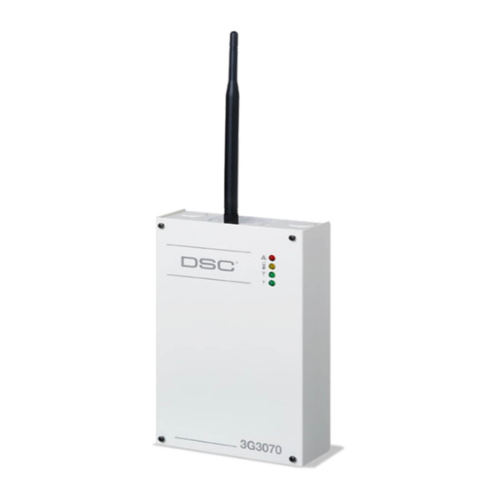
Page 5: Identification Of Parts
OPEN OFF ON NOTE: For UL/ULC installa- tions, connections between the alarm control panel out- puts (telephone interface Tip/Ring, output relay con- tacts) and 3G3070 inputs (Tip/Ring, Z1-Z4) shall be PGM1 PGM2 PGM3 PGM4 AUX+ TAMPER + DC IN -... -
Page 6: Description
4 hours standby power capabilities. An example of a suitable listed compatible control unit is the DSC Model PC1864 with an AUX output rated 11.1 - 12.6VDC. An example of a suitable Listed power supply is DSC Model PC5204 with an AUX output rated 11.6 - 12.6VDC. -
Page 7: Installing The 3G3070
NOTE: Electrical current drawn from this terminal is drawn directly from the power supply. This must be added to the 3G3070 current when determining the total draw on the host panel or power supply. Jumper JP3 does not limit the electrical current available on this output. -
Page 8: Status Leds
‘No Service’. If this LED flashes, the following list indicates the specific trouble based on the number of flashes, by priority. When turned on, the 3G3070 checks for the trouble conditions to be restored in the order listed below. The 3G3070 indicates the status of the highest priority, unrestored trouble condition with the corresponding number of flashes of the red LED. -
Page 9: Operating Principles
• The central station receiver acknowledges the alarm and sends a command to the 3G3070 to gen- erate the corresponding 1400Hz Kiss-off signal for a minimum of 800msec. After the 3G3070 generates a Kiss-off signal, it sends the next alarm or, if no further alarms need to be sent, the control panel goes on-hook. -
Page 10: Outputs
The 3G3070 has four open collector outputs capable of a maximum of 50mA. Internal events on the 3G3070 can trigger the outputs to turn on an LED or activate an input on the host panel. The default settings are as follows. -
Page 11: Low Power Radio Shutdown
YELLOW light will flash one time when the signal is transmitted and two times when it gets a kiss-off. SIM – the SIM should be activated at least 24 hours prior to installation. The 3G3070 will not show signal strength until the SIM is active. - Page 12 • When used as the primary communicator, the yellow light will always be • When used as a backup communicator, the yellow light will be ON when there is a no phone line connected to the 3G3070 TIP and RING, or the line voltage goes below 2.8VDC.
- Page 13 3G3070 low battery trouble (one flash) and an insufficient signal strength trouble (four flashes) are present; the red light will flash one time. Once the 3G3070 low battery trouble condition is corrected, the red light will then begin flashing four times.
- Page 14 • The lights will continue to flash in this sequence until the battery is charged above 12.4VDC Swinger Shutdown for Telephone • If the 3G3070 is configured as a backup, it can send a maximum of 3 TLM troubles and restorals per day Line Monitor (TLM) transmissions for •...
-
Page 15: 3G3070 Wiring Diagrams
3G3070 Wiring Diagrams Figure 2 - Wiring Diagram... - Page 16 CMC. 3. Output 4 on the 3G3070 must be set as “Active High” (default). 4. When powering the 3G3070 Radio by an...
- Page 17 - 24h Test Transmission must be enabled on the dialler and on the 3G3070. Figure 6 - DSC Subscribers’ Unit Fire and GSM Transmitter Mounted in the Same Room Wiring Diagram for DSC Subscribers’ Unit Fire and GSM Transmitter (Passive Communication System)
- Page 18 3G3070 Wiring Diagrams Figure 7 - DSC Subscribers’ Unit Fire and GSM Transmitter Mounted Remotely Alternate Wiring Diagram for DSC Subscribers’ Unit Fire and GSM Transmitter Passive Communication System -Using Phone Line Supervision Relay AUX Power GSM Network Fire Alarm...
- Page 19 3G3070 Wiring Diagrams Figure 8 -Connection Details for GSM Supervision Relay and Redundant Fire Alarm Transmission Connection Details for GSM Supervision Relay & Redundant Fire Alarm Transmission 3G3070 L1 L2 L3 L4 O1 O2 O3 O4+OC 12 13 19 20...
- Page 20 3G3070 Wiring Diagrams Figure 9 - Connection Details for GSM Supervision Relay, Phone Line Supervision and Redundant Fire Alarm Transmission Connection Details for GSM Supervision Relay, Phone Line Supervision Relay and Redundant Fire Alarm Transmission 3G3070 O1 O2 O3 O4+OC...
- Page 21 IMPORTANT READ CAREFULLY: DSC Software purchased with or without Products and Components is copyrighted and is purchased under the following license terms: • This End User License Agreement ("EULA") is a legal agreement 3. COPYRIGHT between You (the company, individual or entity who acquired the Soft-...
- Page 22 This equipment generates and uses radio frequency energy the end user. and if not installed and used properly, in strict accordance with the DSC c/o APL Logistics, 757 Douglas Hill Rd., Lithia Springs, GA 30122 manufacturer's instructions, may cause interference to radio and Additional Information television reception.
- Page 23 Access cards or tags returned for replace- purchase, the product shall be free of defects in materials ment under warranty will be credited or replaced at DSC's and workmanship under normal use. During the warranty option. Products not covered by this warranty, or other-...
Need help?
Do you have a question about the 3G3070 and is the answer not in the manual?
Questions and answers