
Related Manuals for Quantum i8


Summary of Contents for Quantum i8
- Page 1 Digital proportional radio control transmitter INSTRUCTION MANUAL WARNING: This product is only for 15 years old or above...
- Page 2 Digital proportional radio control system Thank you for purchasing our product, an ideal radio system for beginners or experienced users alike. Read this manual carefully before operation in order to ensure your safety, and the safety of others or the safe operation of your system.
- Page 3 Table of Contents 1. Safety ..............................4 1.2 Safety Guide ............................... 4 2. Introduction ............................. 6 2.1 System Features ..............................6 2.2 Transmitter Overview ............................ 7 2.2.1 Transmitter Antenna..........................7 2.2.2 Sticks ................................. 8 2.2.3 Status Indicator ............................8 2.2.4 Channel 5 6 Position Knob ......................... 8 2.2.5 Knob Position Indicator LEDs ......................
-
Page 4: Safety
Digital proportional radio control system 1. Safety 1.2 Safety Guide Mandatory Prohibited • Do not fly at night or in bad weather like rain or thunderstorm. It can cause erratic operation or loss of control. • Do not use the product when the visibility is limited. •... - Page 5 • Misuse of this product can lead to serious injuries or death. To ensure the safety of you and your equipment, read this manual and follow the instructions. • Make sure the product is properly installed in your model. Failure to do so may result in serious injury.
-
Page 6: Introduction
Digital proportional radio control system 2. Introduction The i8 is an 8-channel 2.4GHz AFHDS 2A digital proportional R/C system. It is compatible with multirotors, helicopters, fixed-ring, and gliders. 2.1 System Features The AFHDS 2A (Automatic Frequency Hopping Digital System Second Generation) developed and patented by FLYSKY is specially developed for all radio control models. -
Page 7: Transmitter Overview
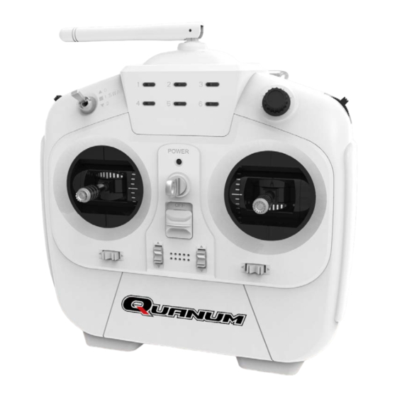
2.2 Transmitter Overview 2.2.1 Transmitter Antenna Precautions: For best signal quality, make sure that the antenna is at about a 90 degree angle to the model. Do not □ point the antenna directly at the receiver. Never grip the transmitter antenna when operating a model. It significantly degrades the RF signal □... -
Page 8: Sticks
Digital proportional radio control system 2.2.2 Sticks There are two sticks on the transmitter and two preset modes for the functions of the sticks. You can switch the sticks to suit your operation habit. For details, refer to section 4.4 Switching the Stick Modes . You can also loose or tighten the lever head to adjust the length of the stick. -
Page 9: Knob Position Indicator Leds
2.2.5 Knob Position Indicator LEDs The knob position indicator LEDs are used to indicate the currently position of the channel 5 6 position knob, each indicator corresponds to a flight mode. When the knob changes position, the corresponding indicator lights up. 2.2.6 Trims There are 4 trims affecting stick functionality, one for rudder (Channel 4), elevator (Channel 2), throttle (Channel 3) and ailerons (Channel 1). -
Page 10: Getting Started
Digital proportional radio control system 3. Getting Started Before operation, install the battery and connect the system as instructed below. 3.1 Transmitter Battery Installation Danger • Only use specified battery. Danger • Do not open, disassemble, or attempt to repair the battery. Danger •... -
Page 11: Connecting The Receiver And Servos
3.2 Connecting the Receiver and Servos Connect the receiver and the servos as indicated below: (CH8) (CH7) (CH6) (CH5) (CH4) (CH3) (CH2) (CH1) -
Page 12: Operation Instruction
Digital proportional radio control system 4. Operation Instruction After setting up, follow the instructions below to operate the system. 4.1 Power On Follow the steps below to turn on the system: Check the system and make sure that: ▫ The battery is fully charged and installed properly. ▫... -
Page 13: Switching The Stick Modes
4.4 Switching the Stick Modes There are two sticks on the transmitter and two preset modes for the functions of the sticks. Usually the stick with the self centring feature on both axis will be mapped to the Elevator, while the other to the Throttle. -
Page 14: Calibrating The Sticks And Knobs
Digital proportional radio control system 4.5 Calibrating the Sticks and Knobs After switching the stick modes, it is required to calibrate the sticks and knobs on the transmitter. You should also perform a calibration after switching sticks or if the transmitter sticks/knobs are not working accurately. -
Page 15: Reversing Channels
4.9 Reversing Channels You can reverse the direction of channels 1, 2, 3 or 4 in relation to the sticks. For example, if a servo is mounted upside down in order to fit inside a model, when the corresponding stick is moved, the servo will move in the oppisite direction. -
Page 16: Product Specification
Digital proportional radio control system 5. Product Specification 5.1 Receiver Specification No. of Channels Model type Multicopter/Fixed-wing/Glider/Heli 2.4 GHz Protocol AFHDS 2A Output PWM/CPPM Voltage range 4.0-6.5V Dimension 25*8.1*44.5mm Weight 13 grams Certificate CE0678, FCC and C-TICK 5.2 Transmitter Specification Model type Multicopter/Fixed-wing/Glider/Heli 2.4 GHz... -
Page 17: Appendix 1 Fcc Statement
Appendix 1 FCC Statement This equipment has been tested and found to comply with the limits for a Class B digital device pursuant to part 15 of theFCC rules. These limits are designed to provide reasonable protection against harmful interference in a residential installation. This equipment generates, uses and can radiate radio frequency energy and, if not installed and used in accordance with the instructions, may cause harmful interference to radio communications. - Page 18 Digital proportional radio control system Edition: 2015-9-22...
Need help?
Do you have a question about the i8 and is the answer not in the manual?
Questions and answers