Table of Contents
Advertisement
Quick Links
Download this manual
See also:
Owner's Manual
SERVICE MANUAL
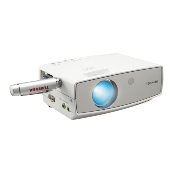
LED DATA PROJECTOR
TDP-FF1A
The above models are classified as green product (s) (*1), as indicated by the underlined serial number (s).
This Service Manual describes replacement parts for green product (s). When repairing any green product (s), use
the parts described in this manual and lead-free solder (*2).
For (*1) and (*2) , see the next page.
© TOSHIBA CORPORATION
FILE NO. 330-200603GR
Published in Japan, March 2006 GREEN
Advertisement
Table of Contents

Related Manuals for Toshiba TDP-FF1A


Summary of Contents for Toshiba TDP-FF1A
-
Page 1: Service Manual
This Service Manual describes replacement parts for green product (s). When repairing any green product (s), use the parts described in this manual and lead-free solder (*2). For (*1) and (*2) , see the next page. © TOSHIBA CORPORATION Published in Japan, March 2006 GREEN... - Page 2 Hazardous Substances. From July 1, 2006, the RoHS Directive will prohibit any marketing of new products containing the restricted substances. Increasing attention is given to issues related to the global environmental. Toshiba Corporation recognizes environmental protection as a key management tasks, and is doing its utmost to enhance and improve the quality and scope of its environmental activities.
- Page 3 Preface This manual is applied to FF1 0.55” DMD SVGA (S8) digital projection system. It’ s the mode of single Panel, Osram LED module and 800(H) x 600(V) resolution. The manual gives you a brief description of basic technical information to help in service and maintaining the product. Your customers will appreciate the quick response time when you immediately identify prob- lems that occur with our products.
- Page 4 Table of Contents Chapter 1 Introduction Highlight Mechanical Specifications Electrical Specifications Battery Specifications Optical Specifications Environmental Compatible Mode Chapter 2 Disassembly Process Equipment Needed Disassemble Top Cover, Main Board, Fan Module, LED Board and Speaker Disassemble Front Cover, IR Lens, Engine Module, Focus Ring and DMD Module Disassemble I/O Board, Power Board and Battery Board Chapter 3...
-
Page 5: Chapter 1 Introduction
Chapter 1 Introduction 1-1 Highlight Item Description One panel 0.55” DMD SVGA projection system with 15 ANSI lumens Lamp Osram LE ATB A2A LED module Weight Light weight Approx. 565 Grams, (1.25 lbs) Resolution True 800 x 600 resolution, 16.7M True colors Video capabil- Build-in full screen NTSC/PAL/SECAM/HDTV (480 i/p, 576i/p, 720p, 1080i) video capabilities with a Composite terminal... - Page 6 1-2 Mechanical Specifications Item Description Dimensions 140mm x 48mm (min. front view) x 102mm (WxHxD) Cooling One fan with low system acoustic noise level System Maximum touch temperature follows the UL60950 regulation Provides space for PCB boards, fan, optical engine, speaker and Cabinet Keystone +/ -16 degree...
- Page 7 Item Description TI DDP2000 component set, System Con- Micronas VPX3226 Video decoder troller ADI AD9883 compatible A/D converter Atmel AT76C120 Digital Image Processor Standards : -NTSC: M (3.58MHz), 4.43 MHz Video Com- -PAL: B, D, G, H, I, M, N patibility -SECAM: B, D, G, K, K1, L -HDTV: 480i/p, 576i/p, 720p, 1080i...
- Page 8 1-5 Optical Specifications Item Description Projection F# 2.6, Fixed Lens. lens Focus 40cm to 2.5m with full optical performance Range 30cm to 4m mechanical travel Throw Ratio Brightness 15 ANSI Lumens ( Typical ) / 12 ANSI Lumens ( Minimum) Contrast 1500:1 Typical / 1000:1 Minimum (Full on / full off) Uniformity...
-
Page 9: Environmental
1-6 Environmental Item Description Tempera- Operating: 5 - 35°C ture Storage: -20- 60°C Maximum Operating: 5 - 35°C, 80% RH (Max.), non-condensing Humidity Storage: -20 - 60°C, 80%RH (Max.), non-condensing Acoustic 30+/-2 dB(A), typical, at 23 +/-2 degree C. noise level Lamp life >10,000 Hours Operating 0~2,500 ft, for 5°C~35°C... -
Page 10: Compatible Mode
1-7 Compatible Mode Analog Compatibility Resolution V-Sync[Hz] H-Sync[KHz] 640x350 31.5 640x350 37.9 640x400 37.9 640x480 31.5 640x480 37.9 640x480 37.5 640x480 43.3 720x400 31.5 720x400 37.9 SVGA 800x600 35.2 800x600 37.9 800x600 48.1 800x600 46.9 800x600 53.7 1024x768 48.4 1024x768 56.5 1024x768 1024x768... -
Page 11: Chapter 2 Disassembly Process
Chapter 2 Disassembly Process 2-1 Equipment Needed Item Photo Item Photo Screw Bit Hex Sleeves (+) :107 Sleeves Tweezers... -
Page 12: And Speaker
2-2 Disassemble Top Cover, Main Board, Fan Module, LED Board and Speaker Procedure Photo Unscrew 2 screws to re- move VGA Cover. Left Side Left Side Rear Side Bottom Side Unscrew 6 screws to re- move Top Cover. Move rightwards Note: Please remove Top Cover rightwards. - Page 13 Procedure Photo Unscrew 3 screws and un- plug 1 connector to remove Main Board. Fan Module Main Board...
- Page 14 Procedure Photo Hex screw Unscrew 3 screws, 1 hex screw and unplug 1 connec- tor to remove LED Board LED Board Remove Speaker, Rubber and Mesh directly Rubber Speaker Mesh...
-
Page 15: And Dmd Module
2-3 Disassemble Front Cover, IR Lens, Engine Module, Focus Ring and DMD Module Procedure Photo Loosen 3 tenons to remove Front Cover and IR Lens. IR Lens Front Cover Unscrew 4 screws to re- move Engine Module and unplug 1 connector from En- gine Module. - Page 16 Procedure Photo Unscrew 3 screws to re- move Focus Ring Focus Ring Unscrew 4 hex screws to remove DMD Board, DMD Chip and so on. DMD Socket DMD Mask Note: please re-assemble the parts in the diagonal way. DMD Antidusk DMD Board Rubber Rubber...
-
Page 17: Disassemble I/O Board, Power Board And Battery Board
2-4 Disassemble I/O Board, Power Board and Battery Board Procedure Photo Unscrew 2 screws to re- move I/O Board I/O Board I/O Board Bracket Unscrew 4 hex screws to remove Power Board Power Board... - Page 18 Procedure Photo Notice: please set “Power Switch” button to “OFF” status before disassembling Battery Board. 1. Unscrew 3 screws and 2 hex screws 2. Use a tweezers to take off Battery Connector Cover while lifting Battery Board. 3. Remove Battery Board in the upper right direction.
- Page 19 Procedure Photo Unscrew 1 screw to remove Micro Switch and Micro Switch Frame Micro Switch Frame Micro Switch Loosen Elevator Foot Rub- Elevator Foot Rubber...
-
Page 20: Chapter 3 Troubleshooting
Chapter 3 Troubleshooting 3-1 Equipment Needed - PC or Pattern Generator - DVD Player (Video, S-Video, Audio) - Quantum Data 802B or CHROMA 2327 3-2 Main Procedure Symptom Procedur - Check Battery or Power source (DC 15V) - Ensure all connectors are securely connected and aren’t broken No Power - Check Battery Board... - Page 21 Symptom Procedure Mechanical Noise - Check Fan Module - Check if the DMD Chip and the DMD Board are assembled properly Line Bar / Line - Check DMD Board Defect - Check DMD Chip - Check Main Board - Do “Reset” of the OSD Menu - Ensure the Signal Cable and Source work - Check Battery Board Image Flicker...
-
Page 22: Led / Icon Message
Symptom Procedure - Do “Reset” of the OSD Menu Function Abnormal - Check Main Board - Check DMD Board Note: LED/Icon Message LED message Auto Check Shutdown Icon Condition TEMP BATT. POWER Procedure symptom (Red) (Red) (Green) Display message Flash Check Battery empty and shout... -
Page 23: Chapter 4 Function Test And Alignment Procedure
Chapter 4 Function Test & Alignment Procedure 4-1 Test Equipment Needed - IBM PC with SXGA resolution (Color Video Signal & Pattern Generator) - DVD player with Multi-system (NTSC/PAL/SECAM), equipped “Component”, “S-Video” and “Composite” - HDTV Tuner or Source (480P) - Minolta CL-100 - Quantum Data 802B or CHROMA2327 - After changing parts, check the information below. -
Page 24: Test Condition
4-3 Test Condition - Circumstance Brightness : Dark room less than 2.5 lux. - Inspection Distance : 0.4~2.5 for functional inspection - Screen Size : 60 inches diagonal (wide) - After repairing each unit, it should be burn-in (Refer to the table below). Symptom Burn-in Time Normal Repair... - Page 25 Step Specifica- Procedure Photo tion - Test Signal : The text in 800x600@60Hz the corner - Test Pattern : Text should be Pattern Focus clear after - Adjust the center adjust the clearly; meanwhile, focus ring. one slightly vague corner in the image is allowed.
- Page 26 Specifica- Step Procedure Photo tion 2. Gain G adjust the bright color level of green 3. Gain R adjust the bright color level of blue 4. Gain R adjust the dark color level of red Color 5. Gain R adjust the dark color Perfor- level of green mance...
- Page 27 Specifica- Step Procedure Photo tion - Test Signal : 800x600@60Hz - Test Pattern : Gray 10 The unit Pattern can’t accept - Please check and see if Light the leakage the light leaks *Note Leak is brighter - The unit cannot accept than Gray 10 the leakage is brighter pattern...
- Page 28 Specifica- Step Procedure Photo tion Con- Gray level - Test Pattern : 64 trast/ should be RGBW scale Bright- distinguish- ness able and without color abnormal. R, G, Each R, G, B - Test Pattern : R, B and color should G, B and White White be normal...
- Page 29 Specifica- Step Procedure Photo tion Blem- The bright - Test Pattern : blemish Full Black / cannot be Gray 30 accepted if the problem appear with Gary 30 pat- tern Blem- The dark - Test Pattern : Full blemish white / Blue 60 (Dark) cannot be accepted if...
-
Page 30: Chapter 5 Firmware Upgrade Procedure
Chapter 5 Firmware Upgrade Procedure Equipment Needed Software : - DLP Composer (V3.6 version or up) - FF1 Firmware - Flash Device parameters.txt (copy to the route where DLP composer lite lies) Note: please do keep original Flash Device paramters.txt file for other modles) Hardware : - Power Cord - Mini USB - USB(A) (42.86102.001) -
Page 31: Hardware Setup Procedure
Hardware Setup Procedure Connect USB Cable of PC to USB port of FF1 Projector. Connect Power Cord to FF1 unit. Hold Menu and right buttons and turn on “Switch” button. When Power LED lights green and Temp LED lights red, release two buttons. Step Procedure Photo... - Page 32 Step Procedure Photo Next Click “Next” button. Reading the “License Agreement” rules, choose “I accept and agree to be bound by Next all the terms and con- ditions of this License Agreement” icon, then click “Next” button. Next Press “Next” Button Next Click “Next”...
-
Page 33: Usb Driver Upgrade Procedure
Step Procedure Photo Next Click “Next” button. The program is execut- Next ing “Initializing” status. 5-3.2 USB Driver Upgrade Procedure Step Procedure Photo 1. Hold “Menu” and “Right” key and turn on power switch till “TEMP” LED is lit in red. Execute the 2. - Page 34 Step Procedure Photo Click “OK”. The USB Next driver updated success- fully. 1. Right click “My Com- puter” on the desktop. Select “Properties” on the popup menu to launch the “System Next Properties” window. 2. Choose “Hardware” and then click “Device Manager”.
-
Page 35: Firmware Upgrade Procedure
Firmware Upgrade Procedure Step Procedure Photo 1. Hold “Menu” and “Right” key and then turn on Power Switch till Execute the “TEMP” LED is lit in red program to enter Download Mode. 2. Execute the “DLP ComposerTM” file. Click “Edit” and “Prefer- Next ences”. - Page 36 Step Procedure Photo Choose “Flash Loader” and click “Browse” to search the FF1-com- Next poser-0.4.1-0.7.7.img” file. Select the item “Skip Boot Loader Area (load all but the first 16KB)”. Click “Reset Bus” to erase the flash memory. Note: Next Note: (Please make sure the setting is as follows) Start: 0x0 End:0x3fff...
- Page 37 Step Procedure Photo After file was download. Please to restart the unit and enter the OSD Menu Next to check the F/W version of FF1. Enter the OSD Menu to Input Resolution Finished check the F/W version of Battery info FF1.
-
Page 38: Chapter 6 Spare Part
Chapter 6 Spare Parts Spare Parts List No Location No Parts Code Description E001 23587983 ASSY ENGINE MODULE FF1 U001 23587984 PC BOARD DMD E002 23587985 YM12 SVGA FIX LENS E003 23587256 PARTS DMD SOCKET E004 23587378 SERVICE PARTS DMD RUBBER E005 23587986 DMD MASK SUS301... - Page 39 T O S H I B A C O R P O R A T I O N 1- -1, SHIBAURA 1- - CHOME, MINATO - - KU, TOKYO 105 -- 8001, JAPAN...
Need help?
Do you have a question about the TDP-FF1A and is the answer not in the manual?
Questions and answers