Table of Contents

Summary of Contents for Lectrotab MLC-1
- Page 1 ELECTROMECHANICAL TRIM TAB SYSTEMS Manual Leveling Control Installation/Operation Linear Devices Corporation www.lectrotab.com Phone: 804-368-8428 dba Lectrotab Fax: 804-368-8438 11126 Air Park Road, Suite G Ashland, VA 23005...
- Page 2 Table of Contents • Introduction………………………………………….3 • Safety…………………………………………….…..…3 • How Do Trim Tabs Work………………………..4 • Display Panel Installation & Wiring..…..….5 • Verify Display Settings/Operation..………..6 • Programming Display…………………..………..8 • Programming Chart……………………….……….9 • Troubleshooting……………………..…………..10 • Specifications….……………………..……………..10...
-
Page 3: Introduction
• Control remembers and deploys tabs automatically to last tab setting when ignition key switch is turned off and back on (programmably selected) • Actuators connect directly to display (MLC-1 for single actuator system does not require a control box) •... -
Page 4: How Do Trim Tabs Work
How Do Trim Tabs Work Boaters will enjoy many performance and efficiency benefits by adding Lectrotab trim tabs. Lectrotab trim tabs improve fuel efficiency, increase boat speed, accelerate shallow water planing, eliminate porpoising, and enhance the overall boating experience with a more comfortable ride. -
Page 5: Display Panel Installation & Wiring
Wiring Display Panel: Refer to wiring diagram as shown above for the MLC-1 wiring connections. The red (+12vdc or +24vdc) wire from the boat’s fuse panel and black battery negative wires should be a minimum size of 14 AWG (2.5mm²). -
Page 6: Programming Chart
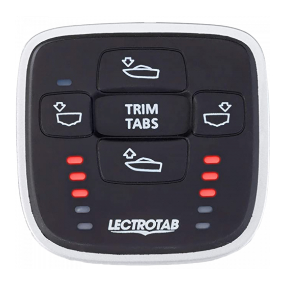
Terminal 7 must be connected to ignition key run position or accessory switch to automatically retract the tabs when key is switched to OFF. Verify Display Settings and Operation MLC-1 (Single actuator, Single station) Photo sensor to Adjust Bow Down or Bow automatically brighten Up Buttons. - Page 7 LED Position Indicators: When retracting actuators/tabs, the top LED indicator will flash to show tabs are retracting. When deploying actuators/tabs, the lowest lit LEDs will flash to show tabs are deploying. Automatic Tab Retraction: There are a couple options for automatically retracting the trim tabs. You may connect the accessory terminal of the ignition key switch to terminal #7 at the MLC keypad.
- Page 8 Programming MLC-1 (Single actuator, Single station) Press top and bottom buttons Press and release left button simultaneously for 4 seconds to to adjust between “Settings” enter program mode and again L1=top left LED, L2=second to exit and save. left LED down, L3=third left Press and release right button to change Setting Value.
- Page 9 Enter, Adjust and Exit Program Mode: • Before entering program mode, 12vdc or 24vdc must be applied to MLC terminals 1, 2 and 7 (see wiring) • Press and hold Bow Down (top) button and Bow Up (bottom) button for 4 seconds to enter program mode •...
-
Page 10: Troubleshooting
MLC-1 Troubleshooting • Error Code: If the MLC control senses a fault, an LED indicator will show a quick repetitive flash. See display below for flashing LED error code Quick flashing LED indicates trim tab actuators are not connected properly (see wiring diagram).


Need help?
Do you have a question about the MLC-1 and is the answer not in the manual?
Questions and answers