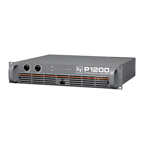
Electro-Voice P1200 Owner's Manual
Precision series
Hide thumbs
Also See for P1200:
- Owner's manual (23 pages) ,
- Brochure & specs (4 pages) ,
- System application manual (24 pages)
Table of Contents
Advertisement
Available languages
Available languages
Quick Links
Advertisement
Chapters
Table of Contents

Summary of Contents for Electro-Voice P1200
- Page 1 OWNER‘S MANUAL BEDIENUNGSANLEITUNG P1200 PRECISION SERIES...
-
Page 2: Table Of Contents
CONTENTS IMPORTANT SAFETY INSTRUCTIONS ....... IMPORTANT SERVICE INSTRUCTIONS ....... DESCRIPTION ....... UNPACKING & WARRANTY ....... FRONT PANEL ....... REAR PANEL ....... INPUT ....... PARALLEL ..........POWER AMP OUTPUT BRIDGED MODE ....... GROUND-LIFT SWITCH ....... SPECIFICATIONS ....... BLOCK DIAGRAM ....... DIMENSIONS ....... -
Page 3: Important Safety Instructions
IMPORTANT SAFETY INSTRUCTIONS The lightning flash with arrowhead symbol, within an equilateral triangle is intended to alert the user to the presence of uninsulated “dangerous voltage“ within the product’s enclosure that may be of sufficient magnitude to constitute a risk of electric shock to persons. The exclamation point within an equilateral triangle is intended to alert the user to the presence of important operating and “maintenance”... -
Page 4: Description
DESCRIPTION Thank you very much for choosing an EV PRECISION SERIES amplifier. We are sure it will give you many years of satisfying performance. EV power amplifiers of the PRECISION SERIES meet the stringent requirements of tough touring applications. They are protected against over-temperature, overload, shorted outputs, radio frequency interference and DC faults. -
Page 5: Front Panel
FRONT PANEL 1. Level Control Calibrated detented potentiometers to alter the total gain of the power amplifier. In order to avoid distortion in mixing consoles upstream, these controls should normally be positioned between 0 dB and -6 dB. The calibrated markings show the additional attenuation directly. 2. -
Page 6: Rear Panel
REAR PANEL REAR SIDE Power amplifier input connectors XLR connectors (male) are provided for “Looping” the signal to other power amplifiers. These are wired parallel to the XLR input connectors in each channel. The inputs of the power amplifier are electronically balanced and wired according to IEC 268. -
Page 7: Power Amp Output
REAR PANEL POWER AMPLIFIER OUTPUT CONNECTORS SPEAKON output connectors are provided for the power amplifier channels A (left) and B (right).The Bridged Out connector for bridged operation is sealed with a plastic cover to prevent connection errors. WARNING: Please make sure not to hook Speakers up to the BRIDGED OUTput in NORMAL mode or damage will result. - Page 9 BEDIENUNGSANLEITUNG P1200 PRECISION SERIES...
- Page 10 INHALTSVERZEICHNIS WICHTIGE SICHERHEITSHINWEISE ....... WICHTIGE SERVICEHINWEISE ....... BESCHREIBUNG ....... AUSPACKEN UND GARANTIE ....... FRONTSEITE ....... REARSEITE ....... EINGANG ....... PARALLEL ..........AUSGANG BRIDGED MODE ....... GROUND-LIFT SCHALTER ....... SPECIFICATIONS ....... BLOCK DIAGRAM ....... ABMESSUNGEN .......
-
Page 11: Wichtige Sicherheitshinweise
WICHTIGE SICHERHEITSHINWEISE Das Blitzsymbol innerhalb eines gleichseitigen Drei- ecks soll den Anwender auf nicht isolierte Leitungen und Kontakte im Geräteinneren hinweisen, an denen hohe Spannungen anliegen, die im Fall einer Berührung zu lebensgefährlichen Stromschlägen führen können. Das Ausrufezeichen innerhalb eines gleichseitigen Dreiecks soll den Anwender auf wichtige Bedienungs- sowie Servicehinweise in der zum Gerät gehör- enden Literatur aufmerksam machen. -
Page 12: Beschreibung
Wir möchten Ihnen zu allererst danken und Sie beglückwünschen, daß Sie sich für die Endstufen der EV PRECISION SERIE entschieden haben. Die Electro-Voice - Endstufen der PRECISION SERIE erfüllen auch die extremen Anforderungen harten Tour-Betriebs. Sie sind gegen Überhitzung, Überlast, Kurzschluß sowie Hochfrequenz und Gleichspannung am Ausgang geschützt. -
Page 13: Frontseite
FRONTSEITE 1. Pegel-Regler Geeichte Rastpotis zur Veränderung der Gesamtverstärkung der Endstufe. Zur Vermeidung von Verzerrungen in vorgeschalteten Mischpulten sollten diese Regler normalerweise zwischen 0dB und -6dB eingestellt werden. Die geeichte Beschriftung zeigt unmittelbar die zusätzliche Reglerdämpfung mit der die intern festgelegte Verstärkung verändert wird. 2. -
Page 14: Rearseite
RÜCKSEITE RÜCKSEITE Endstufeneingangsbuchsen Parallel zu den XLR Eingangsbuchsen ist jeweils eine Buchse zum „Weiterschleifen“ zu weiteren Endstufen vorgesehen. Die Eingänge der Endstufe sind elektronisch symmetrisch ausgeführt und nach der IEC Norm 268 beschaltet. Zur Beseitigung von Brummstörungen in größeren Anlagensystemen können Übertrager nachgerüstet werden. -
Page 15: Ausgang
RÜCKSEITE ENDSTUFENAUSGANGSBUCHSEN Für die Endstufenkanäle A (Links) und B (Rechts) sind jeweils SPEAKON Ausgangsbuchsen vorhanden. Die BRIDGED OUT Buchse für den Brückenbetrieb ist mit einem Kunststoffdeckel geschlossen, um Anschlußfehler zu vermeiden. WARNING: Please make sure not to hook Speakers up to the BRIDGED OUTput in NORMAL mode or damage will result. -
Page 16: Specifications
SPECIFICATIONS TECHNICAL SPECIFICATIONS at rated output power 8ohms, one channel driven, unless otherwise specified Output Power (20Hz - 20kHz / THD ≤ 0,1%) P 1200 into 8 Ohms 2 x 350 W into 4 Ohms 2 x 500 W into 8 Ohms bridged 1 x 1000 W Output Power (1kHz / THD = 1,0%) -
Page 17: Block Diagram
BLOCK DIAGRAM... -
Page 18: Dimensions
DIMENSIONS Dimensions in mm (inch) - Page 20 Bosch Communications Systems Americas–Headquarter Americas Europe, Africa & Middle-East Asia & Pacific Rim–Headquarter Asia Telex Communications, Inc. Headquarter EAME Singapore: Telex Communications (SEA) Pte Ltd 38C Jalan Pemimpin 12000 Portland Ave South, EVI Audio GmbH Singapore 577180 Burnsville, MN 55337, USA Hirschberger Ring 45, D-94315, USA–Ph: 1-800-392-3497 Straubing, Germany...


Need help?
Do you have a question about the P1200 and is the answer not in the manual?
Questions and answers