Table of Contents
Advertisement
www.weiderfitness.com
Model No. WESY1938C.0
Serial No.
Write the serial number in the
space above for reference.
Serial Number Decal (under seat)
ACTIVATE YOUR
WARRANTY
To register your product and
activate your warranty today,
go to www.iconservice.ca.
CUSTOMER SERVICE
Call toll-free 1-888-936-4266
Mon.–Fri. 7:30 a.m.–4:30 p.m. ET
(excluding holidays)
or email us at
customerservice@iconcanada.ca
Please do not contact the store.
CAUTION
Read all precautions and
instructions in this manual before
using this equipment. Save this
manual for future reference.
USER'S MANUAL
Advertisement
Table of Contents

Subscribe to Our Youtube Channel
Related Manuals for Weider WESY1938C.0


Summary of Contents for Weider WESY1938C.0
- Page 1 Model No. WESY1938C.0 Serial No. USER’S MANUAL Write the serial number in the space above for reference. Serial Number Decal (under seat) ACTIVATE YOUR WARRANTY To register your product and activate your warranty today, go to www.iconservice.ca. CUSTOMER SERVICE Call toll-free 1-888-936-4266 Mon.–Fri.
-
Page 2: Table Of Contents
ATTENTION shown. Note: The decal(s) may not be shown at actual size. Part # 166295 This decal is on both sides of the upright and on the pivot frame. WEIDER is a registered trademark of ICON Health & Fitness, Inc. -
Page 3: Important Precautions
IMPORTANT PRECAUTIONS WARNING: To reduce the risk of serious injury, read all important precautions and instructions in this manual and all warnings on the weight system before using the weight system. ICON assumes no responsibility for personal injury or property damage sustained by or through the use of this product. -
Page 5: Before You Begin
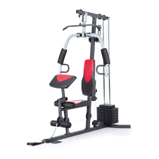
BEFORE YOU BEGIN Thank you for selecting the versatile WEIDER 2980 X reading this manual, please see the front cover of this ® weight system. The 2980 X weight system is designed manual. To help us assist you, note the product model to develop the major muscle groups of the body. -
Page 6: Part Identification Chart
PART IDENTIFICATION CHART Use the drawings below to identify the small parts needed for assembly. The number in parentheses below each drawing is the key number of the part, from the PART LIST near the end of this manual. Note: If a part is not in the hardware kit, check to see if it has been preassembled. -
Page 7: Assembly
ASSEMBLY • Assembly requires two persons. • The following tools (not included) may be required for assembly: • Because of its weight and size, assemble the two adjustable wrenches weight system in the location where it will be used. Make sure that there is enough clearance to walk one rubber mallet around the weight system. -
Page 8: M8 X 63Mm Carriage
Frame Assembly 2. Insert four M8 x 63mm Carriage Bolts (64) up into the Base (1). Note: It may be helpful to place a piece of tape over the bolt heads to hold them in place. 3. Orient the two Weight Guides (21) so that the indicated holes (A) are closer to the lower ends. - Page 9 4. Attach the Front Leg (7) to the Base (1) with the two M8 x 63mm Carriage Bolts (64) and two M8 Locknuts (58); do not tighten the Locknuts yet. Next, hold the Leg Bumper (60) against the Front Leg (7), and turn the Leg Bumper so that it is angled upward (B).
- Page 10 7. Orient the Top Frame (4) so that the welded support (E) is on the bottom. Attach the Top Frame (4) to the Upright (3) with two M8 x 65mm Bolts (68), two M8 Washers (59), and two M8 Locknuts (58); do not tighten the Locknuts yet.
-
Page 11: M8 X 22Mm Shoulder
10. Grease an M10 x 51mm Bolt (66). Attach a Cable Pivot (39) to the Left Arm (10) with the Bolt and Grease an M10 Locknut (56). Do not overtighten the Locknut; the Cable Pivot must pivot easily. Next, wet the inside of a Large Foam Pad (42) with soapy water. - Page 12 13. Route the Arm Cable (54) over a V-pulley (46). Attach the V-pulley, a Large Cable Trap (50), two Full Guards (41), and an M10 Washer (57) to the Upright (3) with an M10 x 63mm Bolt (75) and an M10 Locknut (56).
- Page 13 16. Grease an M8 x 22mm Shoulder Bolt (65). Attach the Arm Cable (54) to the indicated Cable Pivot (39) with the Shoulder Bolt and an M8 Locknut (58). Make sure that the cable end can Grease pivot easily on the Shoulder Bolt. 17.
- Page 14 19. Route the Low Cable (53) under a 90mm Pulley (48) and through the Upright (3). Attach the Pulley inside the Upright with an M10 x 67mm Bolt (71), two M10 Washers (57), two 12mm Spacers (52), and an M10 Locknut (56). 20.
- Page 15 22. Attach the Low Cable (53) to the U-bracket (45) with an M8 Washer (59) and an M8 Locknut (58). See the inset drawing. Do not overtighten the Locknut; it should be threaded onto the end of the Low Cable so that only two threads are showing above the Locknut.
- Page 16 26. Route the High Cable (55) up through the Top Frame (4) and over a 90mm Thin Pulley (47). Attach the Pulley inside the Top Frame with the M10 x 67mm Bolt (71) used in step 24, an 11mm Spacer (49), an M10 Washer (57), and an M10 Locknut (56).
-
Page 17: M4 X 20Mm Self-Tapping
Seat Assembly 29. Attach the Backrest (16) to the Upright (3) with two M6 x 63mm Screws (70) and two M6 Washers (80). 30. Attach the Seat (15) to the Seat Frame (6) with four M6 x 16mm Screws (62). 31. -
Page 18: Part
32. Insert the Pad Tube (29) into the Front Leg (7). Next, slide two Small Foam Pads (28) onto the Pad Tube (29). Then, slide two Small Foam Pads (28) onto the Leg Lever (8). 33. Attach the Curl Pad (14) to the Curl Post (13) with two M6 x 16mm Screws (62). -
Page 19: Adjustment
ADJUSTMENT This section explains how to adjust the weight system. See the EXERCISE GUIDELINES on page 24 for important information about how to get the most benefit from your exercise program. Also, refer to the accompanying exercise guide to see the correct form for each exercise. Make sure all parts are properly tightened each time the weight system is used. - Page 20 USING THE LEG LEVER Before using the low pulley station, engage the Leg Lever Pin (38) into the Leg Lever (8) and the Lock Plate (73). ARM CONVERSION To use the Arms (9, 10) as butterfly arms, insert the Arm Pins (40) into the holes (A) in the Upright (3) and the Pivot Frame (5) as shown.
-
Page 21: Weight Resistance Chart
LOCKING THE WEIGHT STACK Lock the weight stack by inserting the Lock Pin (18) into a Weight Guide (21) and securing the Lock (17) onto the Lock Pin. WEIGHT RESISTANCE CHART The chart below shows the approximate weight resistance at each exercise station. The numbers in the left col- umn refer to the 12.5-lb. -
Page 22: Cable Diagram
CABLE DIAGRAM The diagram below shows the proper routing of the cables. The numbers in each drawing show the proper route of that cable. Cut along the dotted line, and refer to this diagram while you assemble the cables and the pulleys. If the cables and the pulleys are not assembled correctly, the weight system will not function properly and damage may occur. -
Page 23: Maintenance
MAINTENANCE Make sure that all parts are properly tightened each time the weight system is used. Replace any worn parts immediately. The weight system can be cleaned with a damp cloth and a mild, non-abrasive detergent. Do not use solvents. TIGHTENING THE CABLES Woven cable, the type of cable used on the weight system, can stretch slightly when it is first used. -
Page 24: Exercise Guidelines
EXERCISE GUIDELINES FOUR TYPES OF STRENGTH WORKOUTS to determine the appropriate length of time for each workout, and the numbers of repetitions and sets to Note: A “repetition” is one complete cycle of an complete. Progress at your own pace and be sensitive exercise, such as one sit-up. -
Page 25: Part List
PART LIST Model No. WESY1938C.0 R1016A Key No. Qty. Description Key No. Qty. Description Base Arm Bushing Stabilizer U-bracket Upright V-pulley Top Frame 90mm Thin Pulley Pivot Frame 90mm Pulley Seat Frame 11mm Spacer Front Leg Large Cable Trap Leg Lever... -
Page 26: Exploded Drawing
EXPLODED DRAWING A Model No. WESY1938C.0 R1016A 56 57... - Page 27 EXPLODED DRAWING B Model No. WESY1938C.0 R1016A 41 57 41 75...
-
Page 28: Ordering Replacement Parts
ORDERING REPLACEMENT PARTS To order replacement parts, please see the front cover of this manual. To help us assist you, be prepared to provide the following information when contacting us: • the model number and serial number of the product (see the front cover of this manual) •...
Need help?
Do you have a question about the WESY1938C.0 and is the answer not in the manual?
Questions and answers