Table of Contents
Advertisement
Quick Links
Advertisement
Table of Contents

Related Manuals for Alto MISTRAL 6000


Summary of Contents for Alto MISTRAL 6000
- Page 1 Service MODEL: MISTRAL 6000 www.altoproaudio.com Version 2.0...
- Page 2 CONTENTS 1. Introduction..………………………………………………………….………………..2 2. Specification.…………………………………………………………….……….…….3 3. Schematic Diagram…………….…………………….……….….…………………..4 4. Wiring Diagram..……………….…………….………...…….………………….……11 5. PCB Layout……..……………….…………….………...…….………………….…...13 6. Test Procedure…………..……………………….………………………….……..18 7. Exploded Views & Mechanical Parts List………..……………….…………...20 8. BOM.……………………………………………………………………..………………23...
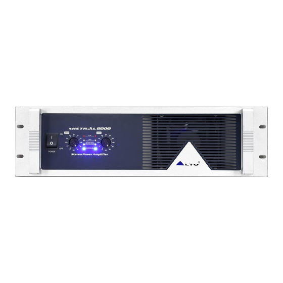
- Page 3 1. Introduction ALTO MISTRAL amplifiers are series of innovative design power amplifiers. This series work under high stability with great power supply in just 2-rack spaces. Airflow is from back to front panel to keep in a nice air circulation inside the Rack. The automatic fan, which affects the temperature of machine includes various kinds of speed, therefore, this low-noise fan makes a good result in cooling the heat from machines.
- Page 4 MODEL MISTRAL6000 20Hz 20KHz@0.1%THD, Stereo Mode 8 ohms per channel(EIAJ) 1070W 4 ohms per channel (EIAJ) 1500W Bridge Mono Mode 8 ohms, 1KHz, 0.1% THD (EIAJ) 3000W Distortion (SMPTE-IM) <0.05% 20Hz-20KHz ± 1dB, -3dB points: 10Hz-60KHz Frequency Response Damping Factor, 1KHz and below >400 at 8ohms Signal to Noise, 20Hz-20KHz 110dB...
- Page 5 -110V_A RECTIFIER BRIDGE1- 10AT JP1_8 R1_2 6.3x32 FUSE HOLDER -V FAN CH1 CN-PCB6.3 R1_1 RELAY POWER1 VAC FAN2-CH1 AC INPUT Titel ALTO MISTRAL6000-CH1 DRIVE PCB# MIS6000.PCB Size Model No: Revision MISTRAL6000 VER050127 27-Jan-2005 Date: Sheet File: MIS60-CH1.Sch Drawn By: C.C.LIN...
- Page 6 -110V_B RECTIFIER BRIDGE2- 10AT R2_2 JP2_8 6.3x32 FUSE HOLDER -V FAN CH2 CN-PCB6.3 R2_1 RELAY POWER2 VAC FAN2 AC INPUT Titel ALTO MISTRAL6000-CH2 DRIVE PCB# MIS6000.PCB Size Model No: Revision MISTRAL6000 VER050203 Date: 3-Feb-2005 Sheet File: MIS60-CH2-050203.Sch Drawn By: C.C.LIN...
- Page 12 MISTRAL6000 Chassis Wiring Drawing (100V-120V) HA03442 GND2 OUT2 GND1 OUT1 HA03433 HA03432 HA03433 HA03432 GRAY GRAY WHITE WHITE GND2 OUT2 GND1 OUT1 GRAY HA01258 HA02471 WHITE WHITE HA01239 HA03431 GRAY HA01237 R1_5 R2_5 BLUE BLACK HA01198 JP1_1 JP2_1 (CH1_OUT) (CH2_OUT) JP1_2 JP2_2 (GND1)
- Page 13 MISTRAL6000 Chassis Wiring Drawing (220V-240V) HA03442 GND2 OUT2 GND1 OUT1 HA03433 HA03432 HA03433 HA03432 GRAY GRAY WHITE WHITE GND2 OUT2 GND1 OUT1 GRAY HA01258 HA02471 WHITE WHITE HA01239 HA03431 GRAY HA01237 R1_5 R2_5 BLUE BLACK HA01198 JP1_1 JP2_1 (CH1_OUT) (CH2_OUT) JP1_2 JP2_2 (GND1)
- Page 19 6. Test Procedure The semi-finished product test procedure 6.1Test Instruments 1. Power supply 2. Digital voltage meter 3. AP (Audio precision) 4. Oscilloscope 5. Two 8Ω(400W) resistors 6.2 Test procedures and specification a. Set LIMITER and BRIDGE switches at the position of OFF, turn the VRs of CH1 and CH2 to maximum, then turn on the power switch, the power LED will be illuminated (blue), OPERATING/PROTECTION LED is illuminated to be red at first, then become green after 2-5 seconds, the fan will be running.
- Page 20 i. Adjust volume VR to the minimum, turn LIMITER switch to the position of ON. Set CH1 and CH2 in short circuit, then adjust the VR volume to the maximum, the LED for LIMITER on the panel will be illuminated, the consumption power should be less than 100W.
- Page 22 No Part No. Description Specification Qty. MA04305 ZC-Panel MISTRAL6000 ALTO-V1.0 MA00028 ZC-Panel MISTRAL6000 ALTO-V1.0 MB03701 ZC-Chassis MISTRAL6000 V-1.1 MC00636 ZC-Top cover MISTRAL6000 V-1.1 MI02404 ZB-handle MISTRAL6000 20*25.5*124V1.0 MI02399 ZB-Fixed bracket MISTRAL6000 L V1.0 MI02397 ZB-Fixed bracket MISTRAL6000 R V1.0 MI02401 ZB-Front panel MISTRAL6000 V1.0...
- Page 23 No Part No. Description Specification Qty. 46 HK04607 K-PCB P-MIS60PWR 47 HK04608 K-PCB P-MIS60SP 48 HK00793 K-PCB P-MIS2500-INPUT 49 HK00787 K-PCB P-MIS2500-INPUT 50 NI01867 Rubber pad 20.5*14*7.6mm(SF-006) 51 NI00389 ZD- plastic washer φ12*φ16*0.5 52 MG00027 Screw M3*12 53 HI00142 A0701HM-15A 54 HE00083 Fan-1225M12S-PC1 DC12V/0.6A 120*120*25mm 360mm...
- Page 24 No. Part No. Description Specification Remark 1 MA04305 panel MISTRAL6000 ALTO_V1.1 2 MA00095 panel MISTRAL600 3 MA00072 panel MISTRAL600_V1.1 4 MI03110 panel 3.1t*133*25.5*1M+5(1M/1.32KG)_V 1.0 5 MA00028 panel MISTRAL6000 ALTO_V1.0 6 MA00099 panel MISTRAL6000 7 MA00036 panel MISTRAL6000_V1.1 8 MJ00088 single light board 1.5*2135*1220 30.67kg 9 MB03701 chassis MISTRAL6000 V_1.1...
- Page 25 No. Part No. Description Specification Remark 42 MJ00059 single light board 1.2*2135*1220 24.54kg 43 NI02650 knob φ18*18mm 10*φ22.5 44 NI02651 knob fix sheath 7P-2 SIZEψ11.0 SJT3C#14 45 NI02853 bushing 46 HI00022 power switch-RS 4p black frame red key 47 SA00200 bridge rectifier 40A/400V BP40-04 48 HA01267...
- Page 26 LT-322+1.5*3C(H05VV-F) 2.27M BK 85 NI00218 cable tie ALT-102SB 86 HJ00006 desiccant 87 NA00280 PE bag 0.05t*820*650mm 88 NB02501 gift carton MISTRAL6000 ALTO 89 NB03193 cushion MISTRAL6000 _V1.0 90 NB03245 carton MISTRAL6000 ALTO_V1.0 91 NE02227 label PSA-31500 220-240V 92 NI00037 adhesive label 0.05*1M...
- Page 27 No. Part No. Description Specification Remark 124 MI03111 heat-sink 127.5*40*1M+5(1M/6.49KG)_V 1.0 15A φ6*32mm UL 125 HD00029 ceramic tube fuse 126 HC00034 short circuit connector NO.2700 2.54mm/6mm OPEN 127 HA01933 jump 2.5mm J1-4,J1-5 128 HC00076 connector(male) 2P 2.5mm 180° JP1-14 129 HC00077 connector(male) 3P 2.5mm 180°...
- Page 28 No. Part No. Description Specification Remark C1-15,C1-16,C1-17,C1-18,C1-19, C1-20,C1-21,C1-22,C1-23,C1-24, 470uF/160V φ18*45mm 167 CB00180 electrolytic capacitor C1-25,C1-26,C1-27,C1-28,C1-29, C1-30 470uF/35V φ10*20mm 168 CB00067 electrolytic capacitor C1-42 220uF/25V φ8*11mm 169 CB00057 electrolytic capacitor C1-8,C1-45 220uF/16V NP φ10*12.5mm 170 CB00171 electrolytic capacitor C1-34 220uF/16V φ8*11mm 171 CB00055 electrolytic capacitor C1-37...
- Page 29 No. Part No. Description Specification Remark 330Ω M type 207 RA00200 fixed resistor 1/4W R1-10,R1-55 330KΩ M type 208 RA00299 fixed resistor 1/4W R1-42,R1-48 47Ω M type 209 RA00174 fixed resistor 1/4W R1-52 47KΩ M type 210 RA00266 fixed resistor 1/4W R1-47 8.2KΩ...
- Page 30 No. Part No. Description Specification Remark metal-oxide-film resistor 1W 6.8KΩ P type 248 RA00020 R2_44 metal-oxide-film resistor 2W 5.6Ω P type 249 RA00051 R2_39 metal-oxide-film resistor 3W 15KΩ P type 250 RA01332 R1_49 metal-oxide-film resistor 3W 1.5KΩ RSS P type 251 RA00063 R1_63 R2_27,R2_28,R2_29,R2_30,R2_31,...
- Page 31 No. Part No. Description Specification Remark 289 SB00023 power transistor 2SA1943-O Q2_5,Q2_6,Q2_7,Q2_8,Q2_4,Q2_3 Q2_9,Q2_10,Q2_11,Q2_12,Q2_13, 290 SB00021 power transistor 2SC5200 Q2_14 291 SD00032 integrated circuit LM317T U2_4 292 SD00173 integrated circuit NJM4580L(JRC) U2_1,U2_2 293 CN00060 fixed inductance L2_1 2uH 10A(CSAF-302824)(φ1.5mm*12 1/2T) 500Ω(TDC5C150L) 294 RH00021 thermistor R2_3 50Ω(TDC05A050J)
- Page 32 No. Part No. Description Specification Remark 332 NC00181 insulator MISTRAL4000 1.6t*136*16mm 333 NC00041 insulation board 1.6t*0.65M*70M 334 MI01954 fixed bracket MISTRAL4000 1.5t*136*16mm right 335 MJ00069 iron board 1.5*2135*1220 30.67kg 336 HA02759 wire 5P-5P 120mm UL1007 24AWG 337 CA00088 ceramic capacitor 100PF/1000V Q2-1,Q2-2 338 HA03434...
- Page 33 No. Part No. Description Specification Remark 375 HA02471 wire 360mm UL1015 14AWG white 376 HA01258 wire 380mm UL1015 14AWG gray 377 HA03432 wire 100mm UL1015 14AWG JP1,JP3 378 HA03433 wire 100mm UL1015 14AWG JP6,JP4 379 HB01396 MIS60SP(2*4)_VER040922 380 AC00002 solder wire 63/37% 381 HK00793 PC board...
Need help?
Do you have a question about the MISTRAL 6000 and is the answer not in the manual?
Questions and answers