Table of Contents
Advertisement
IMPORTANT
Read and save these instructions. This guide should be kept by the installer.
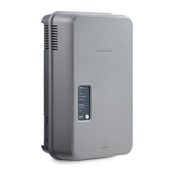
HM750A1000
ADVANCED ELECTRODE STEAM HUMIDIFIER
INTRODUCTION
The HM750 is the most advanced residential steam
humidifier available and provides steady and reliable
humidification for a home. The humidifier is designed for
connection directly to a supply air duct for humidity on
demand. The humidifier may be directly mounted to the air
duct, or remotely from the air duct, with a steam hose
connecting the humidifier to a distributor nozzle installed
at the air duct.
Included in the Box
—
HM750 steam humidifier
—
H6062 HumidiPRO
—
—
Rubber drain hose
—
LDPE water hose
—
Baffle (duct mount only)
—
Foam gasket (duct mount only)
—
Steam hose (wall mount only)
—
Fittings, hardware, and mounting template
—
Installation Instructions, 33-00289 (this document)
—
Annual Operation and Maintenance Reminder
INSTALLATION INSTRUCTIONS
Tools Needed
—
Flat-head screwdriver
—
Phillips screwdriver
—
Wrench
—
Copper pipe (optional)
—
Level
—
Hole saw
Humidifier Configuration
The HM750 is configured at the factory to operate under
most conditions without the need to change its
configuration.
NOTE: Because the humidifier is factory configured for
optimal performance, Honeywell strongly
discourages changes to the configuration of the
humidifier not described in these instructions.
Before Installation
1. Ensure that available voltage and phase
corresponds with humidifier voltage and phase as
indicated on humidifier's specification label.
2. Ensure that the dedicated external fuse disconnect
is of sufficient size to handle the rated amps as
indicated on the specification label. Refer to local
codes.
3. Ensure sufficient clearances will be available as
described in the Location section on page 6.
4. If the humidifier will be wall mounted, ensure steam
lines can be routed to duct as described in the Steam
Line Instructions on page 7.
33-00289-01
Advertisement
Table of Contents

Related Manuals for Honeywell HM750


Summary of Contents for Honeywell HM750
- Page 1 — Level — Hole saw Humidifier Configuration The HM750 is configured at the factory to operate under most conditions without the need to change its configuration. NOTE: Because the humidifier is factory configured for optimal performance, Honeywell strongly discourages changes to the configuration of the humidifier not described in these instructions.
- Page 2 Water quality • Honeywell does not accept any liability for The Honeywell HM750 requires a cold water installations of humidity equipment installed by connection from your home's main water supply unqualified personnel or the use of between 15-100 PSIG.
- Page 3 HM750A1000 Parts and Accessories The following parts and accessories are available and may have been included with your HM750 humidifier. The cylinder is the only item that will need periodic replacement to maintain proper humidifier operation. Table 2. Parts and accessories.
- Page 4 120 V and 22 GPD when run on 240 V. See Figure 20 sized properly. Do not use square feet when sizing for details on configuring the HM750 to run on a different a humidifier installation. Instead, cubic feet must voltage.
- Page 5 240 VAC 240VAC MAIN SUPPLY OFF ON ALWAYS INSTALL L2/N A WATER USE 1/2 IN. OD COPPER SHUT-OFF VALVE. TO WITHIN 4 FT (1.2 M) GROUND OF HUMIDIFIER. (OPTIONAL) ELECTRICAL M37185 Fig. 2. Typical HM750 Installation. Measurements in inches (mm). 33-00289—01...
- Page 6 • When possible, mount the HM750 humidifier at a height convenient for servicing. NOTE: Do not mount on surfaces above 176 °F (80 °C), 1/2 DUCT where freezing can occur, vibrating surface, or floor.
- Page 7 15 ft. (4.6 m) (3.5) * The use of steam line other than Honeywell supplied steam hose line will void the warranty and may adversely affect the operation of the humidifier. NOTE: Condensate is not returned to the humidifier using a separate condensate line. Rather, the condensate is returned to the humidifier via the steam line.
- Page 8 MINIMUM 12 (305) MINIMUM 12 (305) RADIUS MINIMUM RADIUS SUPPORT BRACKETS SUPPORT BRACKETS CONNECT STEAM HOSE TO CYLINDER OBSTRUCTION HM750 Status Idle Filling Humidifying Draining Service Cylinder Fault Power Drain Fault Codes In Front Cover (305) HM750 Status Idle MINIMUM...
- Page 9 HM750A1000 MOUNTING THE HUMIDIFIER The HM750 can be mounted either directly on a supply air 3. Drill a 1-3/4” hole in the duct for the steam duct or remotely mounted on a wall. When remotely distributor nozzle. Attach the steam hose to the...
- Page 10 HM750A1000 Mounting to the Supply Duct The HM750 can also be mounted directly onto the supply INSTALL THE STEAM NOZZLE duct. In this case, the steam guide must be removed and 1. Install the nozzle with baffle directly onto the...
- Page 11 — Drain water is automatically cooled to 160 °F NOTE: To remove the water supply line, the floating tip of (71 °C) when HM750 cycles a drain. When an the fill connection is pushed in slightly, which will emergency drain occurs, temperature may be release the grip on the water supply line.
- Page 12 HM750A1000 ELECTRICAL WARNING To comply with UL product listing, the HM750 must be hardwired to a dedicated 15 amp circuit CAUTION breaker. All wiring must be done per governing Wiring to be performed by a licensed electrician. electrical codes. Failure to do so will void the Installation on a GFCI circuit is recommended.
- Page 13 When distributing steam into a duct, there could be a call solid wire and keep as short as possible. for humidity when there is no air flow. The HM750 with Humidity Control HumidiPRO control or some other thermostat can be •...
- Page 14 NOTE: If a Prestige, VisionPRO, Lyric (or similar) are used to control humidity, wire the two HUM contacts to terminals 1 and 2 on the HM750. With the jumper in place between terminals 1 and 8 on the HM750, only these two wires are necessary to control humidity.
- Page 15 LEDs and sequences. period of time for the HM750 to reach full output capacity. It may take several hours with low • If an error is detected during the self-diagnostic conductivity water.
- Page 16 LED will flash on and off, during which time the humidifier will continue to operate as normal. After 7 The HM750 user interface includes a series of LEDs that days of flashing, the LED will remain on solid, and the provide information about the humidifier status.
- Page 17 HM750A1000 STEAM OUTLET FILL HIGH WATER SENSOR CYLINDER PLUGS STEAM CYLINDER HM750 Status USER Idle Filling INTERFACE Humidifying Draining Service Cylinder POWER/DRAIN Fault BUTTON Power Drain Fault Codes In Front Cover FILL VALVE DRAIN VALVE QUICK DRAIN CONNECTOR OUTLET M37211 Fig.
- Page 18 Accumulation of debris on the strainer can NOTE: As long as the HM750 is powered, it will lead to reduced inlet water flow or complete blockage. automatically drain the cylinder when there has...
- Page 19 AND DRAIN M37222 life will result in improper operation and may result in damage to the humidifier. Honeywell is not responsible for any damages resulting from, or Fig. 27. Measurements in inches (mm). attributed to, the failure to replace a spent cylinder.
- Page 20 HM750A1000 Removing the Cylinder 2. REMOVE CYLINDER 1. LOOSEN PLUGS BY HOSE CLAMP WARNING PULLING VERTICALLY. Disconnect main power source before accessing internal compartments. 3. PULL CYLINDER The inside of the humidifier cabinet contains high AWAY FROM voltage components and wiring. Access should be HOSE BY TILTING limited to authorized personnel.
- Page 21 HM750A1000 Drain Valve Removal (for cleaning or replacement) Always clean the drain valve before installing a new cylinder. Scale from the spent cylinder may have fallen into the drain valve and could prevent its proper operation. To properly clean the drain valve it must be removed and disassembled. WARNING 2.
- Page 22 HM750A1000 Inlet Valve Strainer Cleaning Opening Electrical Compartment Depending on the water quality, periodic cleaning of the fill valve strainer may be required. This can be performed WARNING without removing the valve from humidifier. Disconnect main power source before accessing internal compartments.
- Page 23 HM750A1000 Inlet Valve Replacement 3. SLIDE FORWARD WARNING 1. DISCONNECT Disconnect main power source before accessing SOLENOID internal compartments. WIRING The inside of the humidifier cabinet contains high 4. LIFT UP INLET VALVE voltage components and wiring. Access should be limited to authorized personnel.
- Page 24 • The wiring diagram for your specific humidifier is installed on the inside of the humidifier door. A generic CAUTION copy of the HM750 wiring diagram is also included at Burn and Scalding Hazard. the end of this chapter for reference purposes.
- Page 25 When an abnormal condition occurs that cannot be self- • Press and hold the Power/Drain button for 5 seconds. corrected by the software, the HM750 will turn off power The humidifier will begin to drain and, when drained, to the cylinder, drain the cylinder, and annunciate the fault will power off.
- Page 26 HM750A1000 Service LED Symptom Cause Corrective Action(s) Fault 3 Insufficient Cylinder plugs installed incorrectly Check that cylinder plugs are completely seated flashes Current on cylinder. Fill valve activated Fill valve inlet filter clogged Check fill valve inlet filter and clean if required. for long time, but high water level not reached.
- Page 27 HM750A1000 ORANGE BLACK BLACK ELECTRODES TO CARTRIDGE MAIN SUPPLY L1 L2/N GND STEAM CARTRIDGE AIR PROVING AIR PROVING SW FUSE T2A 250V HUMIDISTAT 24VAC HUMIDISTAT VOLTAGE SELECTION EXTERNAL 120VAC 240VAC IDLE LED FILLING LED HUMIDIFYING LED DRAINING LED TRANSFORMER BLACK BLUE CYLINDER FILL VALVE...
- Page 28 This warranty does not cover removal or reinstallation costs. This warranty shall not apply if it is shown by Honeywell that the defect was caused by damage which occurred while the product was in the possession of a consumer.