Table of Contents
Advertisement
Available languages
Available languages
Advertisement
Chapters
Table of Contents

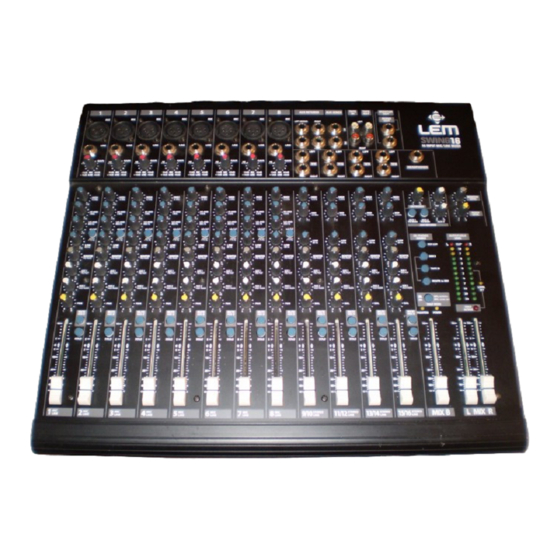
Related Manuals for LEM SWING12


Summary of Contents for LEM SWING12
-
Page 2: Important Safety Instructions
The lighting flash with arrowshad symbol within an equilateral triangle is intended to alert the user to the presence of uninsulated “dangerous voltages” within the product’s enclosure, that may be of sufficient magnitude to constitute a risk of electric schok to persons. The excalamation point within an equilater triangle is intended to alert the user to the presence of important operating and maintenance (servicing) instructions in the... -
Page 3: Table Of Contents
“a secco” un panno morbido o un pennello. Non usate mai alcool, acetone o solventi vari. L’apparato non ha bisogno di ulteriori manutenzioni. ✔ ✔ ✔ ✔ ✔ In caso di avaria Tutte le regolazioni sono esterne ed accessibili alla vostra portata. In caso di avaria non aprite l’apparato, ma rivolgetevi al più vicino Centro di Assistenza Generalmusic/Lem. -
Page 4: Presentazione
Presentazione Presentazione Congratulazioni per l’acquisto di un mixer della Serie SWING! SWING 12 e SWING 16 sono mixer compatti ed estremamente versatili, in grado di offrire un alto numero di funzioni ed un’ottima qualità audio con un layout ergonomico e dimensioni molto contenute. -
Page 6: Canale Di Ingresso Mono
Canale di ingresso MONO Canale di ingresso MONO MIC INPUT Connettore XLR bilanciato: riceve il segnale microfonico in ingresso. Questo ingresso, riservato all'utilizzo di microfoni, può ricevere una vasta gamma di segnali bilanciati o sbilanciati a bassa impedenza. LINE INPUT LINE Connettore JACK sbilanciato: riceve il segnale di linea in ingresso. - Page 7 Canale di ingresso MONO LO CUT Filtro PASSA-ALTO: consente di attenuare le frequenze basse al di sotto dei 75 Hz con una pendenza di 18 dB per ottava. Grazie a questo filtro è possibile eliminare le frequenze subsoniche indesiderate, come ad esempio il rimbombo dei microfoni o le risonanze del palco. Controllo per le frequenze BASSE: consente un guadagno o una attenuazione di 15 dB a 80 Hz con una curva di tipo “SHELVING”.
-
Page 8: Canale Di Ingresso Stereo
Canale di ingresso STEREO Canale di ingresso STEREO LEFT (MONO) STEREO INPUT Connettori JACK: ricevono il segnale STEREO di linea in ingresso (0 dB). 9/10 Inserendo un unico connettore JACK nell’ingresso LEFT, il canale si comporta come un canale MONO. RIGHT MIC / STEREO LINE INPUT (SWING 12) HIGH... -
Page 9: Sezione Master
Sezione MASTER Sezione MASTER AUX SENDS 1&2 Connettori JACK sbilanciati: TAPE TAPE MONITOR AUX RETURNS AUX SENDS questi connettori inviano verso MONO l’esterno la somma dei segnali LEFT (MONO) RIGHT LEFT provenienti dalle corrispondenti mandate AUX dei canali di ingresso. Le mandate AUX sono POST–FADER e, quindi, previste principalmente per l’utilizzo di effetti RIGHT... - Page 10 Sezione MASTER MONITOR LEVEL Potenziometro per il controllo del livello dell’uscita MONITOR. TAPE IN L&R Due connettori RCA: ricevono dall’esterno il segnale di registratori STEREO, CD player, DAT, ecc. Potete collegate questi ingressi alle uscite delle vostre apparecchiature. TAPE OUT L&R Due connettori RCA: inviano verso l’esterno il segnale prelevato dal MIX e destinato, in genere, alla registrazione STEREO.
- Page 11 Sezione MASTER SOLO MODE Selezione della modalità di SOLO: consente di scegliere se l’ascolto e la visualizzazione dei canali selezionati con il tasto SOLO debba essere PRE-FADER (PFL) o POST FADER (AFL) di canale. LEVEL SET Questo LED si accende quando uno o più tasti SOLO sono premuti ed è selezionata la modalità PFL. Questa è...
-
Page 12: Pannello Posteriore
Pannello posteriore Pannello posteriore POWER MAIN OUTPUT INSERT MAIN OUTPUT CONTROL ROOM MIX B CHANNEL INSERT LEFT RIGHT PHANTOM OUTPUT OUTPUT (TIP=SEND / RING=RETURN) MAIN LEFT RIGHT LEVEL +4dBm RIGHT RIGHT LEFT LEFT BALANCED UNBALANCED BALANCED POWER “WARNING“ TO REDUCE THE RISK OF FIRE OR ELECTRIC SHOCK DO NOT EXPOSE THIS PRODUCT TO RAIN OR MOISTURE. - Page 13 Pannello posteriore MIX B OUTPUT Due connettori RCA (SWING 12) o JACK sbilanciati (SWING 16): si tratta di un’uscita master ausiliaria che invia all'esterno il segnale dei canali selezionati tramite il tasto MUTE/B MIX. CHANNEL INSERT Due (SWING 12) o quattro (SWING 16) connettori JACK STEREO: consentono l’utilizzo di processori di segnale esterni (equalizzatori, processori di dinamica, ecc.) sui canali di ingresso MONO (vedi sezione CANALE DI INGRESSO MONO).
-
Page 14: Cavi Di Collegamento
Cavi di collegamento Cavi di collegamento Di seguito sono riportati gli schemi di connessione relativi ai connettori utilizzabili con i mixer SWING. Abbiate cura dei cavi di collegamento, afferrandoli sempre per i connettori, evitando di tirarli lungo il cordone ed avvolgendoli senza nodi o forti torsioni: ne allungherete la vita e l’affidabilità, a vostro assoluto vantaggio. - Page 15 Cavi di collegamento Connettore RCA Cavo a ‘Y’ per INSERT...
-
Page 16: Esempi Di Collegamento
Esempi di collegamento Esempi di collegamento SWING 16 LIVE P.A. SETUP AMPLIFIED MAIN SPEAKERS from MIX L&R OUT to AUX RETURN from AUX SEND DIGITAL EFFECT TAPE TAPE MONITOR AUX RETURNS AUX SENDS MONO HEADPHONES LEFT (MONO) RIGHT LEFT LINE LINE LINE LINE... - Page 17 Esempi di collegamento SWING 12 HOME RECORDING SETUP AMPLIFIED MONITOR SYSTEM from CR OUTPUTS to AUX RETURN from MIX L&ROUT from AUX SEND DIGITAL EFFECT TAPE TAPE MONITOR AUX RETURNS AUX SENDS LEFT (MONO) RIGHT LEFT LINE LINE LINE LINE RIGHT MIC (MONO) LEFT...
-
Page 18: Specifiche Tecniche
Specifiche tecniche SWING 12 • SPECIFICHE TECNICHE SEZIONE LIVELLI & DATI CONNETTORI CANALE DI INGRESSO MONO sensibilità da -10 a -60dB Ingresso MIC XLR-F bilanciato impedenza 1.3 kOhms sensibilità da +10 a -40dB Ingresso LINE JACK bilanciato impedenza 10 kOhms 75Hz, 18dB/oct. - Page 19 Specifiche tecniche SWING 16 • SPECIFICHE TECNICHE SEZIONE LIVELLI & DATI CONNETTORI CANALE DI INGRESSO MONO sensibilità da -10 a -60dB Ingresso MIC XLR-F bilanciato impedenza 1.3 kOhms sensibilità da +10 a -40dB Ingresso LINE JACK bilanciato impedenza 10 kOhms 75Hz, 18dB/oct toni ALTI ±15dB @ 12kHz, SHELVING...
-
Page 20: Schema A Blocchi
Schema a blocchi Schema a blocchi... -
Page 21: Instructions And Installation
✔ ✔ ✔ ✔ ✔ In the event of breakdown All user-adjustable parts are external and easily accessible. Never open the amplifier: you could run the risk of serious electric shocks. In the event of breakdown, contact the nearest GENERALMUSIC/LEM Assistance Centre... -
Page 22: Introduction
Introduction Introduction Congratulations for having chosen a SWING mixer! SWING 12 and SWING 16 are extremely versatile audio mixers able to offer a great number of functions and a high audio quality in a really compact and easy-to-use format. Equipped with 12 and 16 inputs, the SWING mixer offer a complete and professional set of functions including INSERT on the MIC inputs, 4-band EQ, SOLO with AFL and PFL options and balanced MASTER outputs with the choice of XLR or JACK connectors. -
Page 24: Mono Input Channel
MONO input channel MONO input channel MIC INPUT Balanced XLR connector: receives the microphone input signal on the channel. This input is for use with microphones, but can also accept a wide range of balanced or unbalanced low impedance signals. LINE INPUT LINE Balanced JACK connector: receives the line input signal on the channel. - Page 25 MONO input channel LO CUT HI-PASS filter: allows to reduce the frequencies below 75 Hz with a 18 dB / Oct. slope. Thanks to this filter it’s possible to eliminate unwanted subsonic frequencies, like, for examples the microphones rumble due to the stage resonance. LOW frequency control: gives 15dB boost or cut at 80Hz with a “SHELVING”...
-
Page 26: Stereo Input Channel
STEREO input channel STEREO input channel LEFT (MONO) STEREO INPUT JACK connector: receives the STEREO LINE input signal on the channel (0dB). 9/10 Inserting a single JACK connector on the LEFT socket this channel can be used as a MONO channel. RIGHT MIC / STEREO LINE INPUT (SWING 12) HIGH... -
Page 27: Master Section
MASTER section MASTER section AUX SENDS 1&2 Unbalanced JACK connectors: TAPE TAPE MONITOR AUX RETURNS AUX SENDS these connectors feed out the sum MONO of the signals arriving from the LEFT (MONO) RIGHT LEFT relative AUX sends of the input channels. - Page 28 MASTER section TAPE IN L&R Two RCA connectors: receive external signals from STEREO tape recorders, CD player, DAT, etc. These inputs can be connected to the outputs of your equipment. TAPE OUT L&R Two RCA connectors: send out the signal taken from MIX and normally intended for STEREO recording. These outputs can be connected to the inputs of a recorder.
- Page 29 MASTER section LEVEL SET This LED lights when one or more SOLO button are pressed and the PFL mode is selected. This is the typical SOLO mode used to set the input level of the channels. OUTPUT/SOLO LEVEL 12-LED BARGRAPHS. Allows the visualization of the signal assigned to the HEADPHONES and CONTROL ROOM outputs by the SOLO buttons or the CR/PHONES SOURCE buttons (see point 13).
-
Page 30: Rear Panel
Rear panel Rear panel POWER MAIN OUTPUT INSERT MAIN OUTPUT CONTROL ROOM MIX B CHANNEL INSERT LEFT RIGHT PHANTOM OUTPUT OUTPUT (TIP=SEND / RING=RETURN) MAIN LEFT RIGHT LEVEL +4dBm RIGHT RIGHT LEFT LEFT BALANCED UNBALANCED BALANCED POWER “WARNING“ TO REDUCE THE RISK OF FIRE OR ELECTRIC SHOCK DO NOT EXPOSE THIS PRODUCT TO RAIN OR MOISTURE. - Page 31 Rear panel MIX B OUTPUT Two unbalanced RCA (SWING 12) or JACK (SWING 16) connectors: this is an additional master output which sends out the signal of the channels selected with the MUTE/MIX B buttons. CHANNEL INSERT Two (SWING 12) or four (SWING 16) STEREO JACK connectors: allow external devices (equalizer, compressor, etc.) to be used to process the signal of the channels 1-2 of the SWING 12 and the channels 1-4 of the SWING 16 (see MONO INPUT CHANNEL).
-
Page 32: Connector Cables
Connector cables Connector cables The following are wiring diagrams for the connectors used with teh SWING mixers. Take care of the connector cables, always holding them by the connectors and avoiding pulling the wire and avoid knots and twists when coiling them: this gives the advantage of increasing their life and reliability, which is always to your advantage. - Page 33 Connector cables RCA connector ‘Y’ cable for INSERT...
-
Page 34: Connection Examples
Connection examples Connection examples SWING 16 LIVE P.A. SETUP AMPLIFIED MAIN SPEAKERS from MIX L&R OUT to AUX RETURN from AUX SEND DIGITAL EFFECT TAPE TAPE MONITOR AUX RETURNS AUX SENDS MONO HEADPHONES LEFT (MONO) RIGHT LEFT LINE LINE LINE LINE LINE LINE... - Page 35 Connection examples SWING 12 HOME RECORDING SETUP AMPLIFIED MONITOR SYSTEM from CR OUTPUTS to AUX RETURN from MIX L&ROUT from AUX SEND DIGITAL EFFECT TAPE TAPE MONITOR AUX RETURNS AUX SENDS LEFT (MONO) RIGHT LEFT LINE LINE LINE LINE RIGHT MIC (MONO) LEFT LEFT...
-
Page 36: Technical Specifications
Technical specifications SWING 12 • TECHNICAL SPECIFICATIONS SECTION LEVELS & DATA CONNECTORS MONO INPUT CHANNEL sensitivity from -10 to -60dB MIC input Balanced XLR-F impedance 1.3 kOhms sensitivity from +10 to -40dB LINE input Balanced JACK impedance 10 kOhms 75Hz, 18dB/oct. HIGH ±15dB @ 12kHz, SHELVING HI-MID... - Page 37 Technical specifications SWING 16 • TECHNICAL SPECIFICATIONS SECTION LEVELS & DATA CONNECTORS MONO INPUT CHANNEL sensitivity from -10 to -60dB MIC input Balanced XLR-F impedance 1.3 kOhms sensitivity from +10 to -40dB LINE input Balanced JACK impedance 10 kOhms 75Hz, 18dB/oct HIGH ±15dB @ 12kHz, SHELVING HI-MID...
-
Page 38: Block Diagram
Block diagram Block diagram... - Page 39 FEDERAL COMMUNICATIONS COMMISSION NOTE: This equipment has been tested and found to comply with the limits for a Class A digital device, pursuant to Part 15 of FCC Rules. These limits are designed to provide reasonable protection against harmful interference when the equipment is operated in a commercial environment.
- Page 40 Sales Division: 47842 S.Giovanni in Marignano (RN) – Via delle Rose, 12 – tel. +39-0541-959511 – fax +39-0541-957404 Internet: http://www.lemaudio.com...
Need help?
Do you have a question about the SWING12 and is the answer not in the manual?
Questions and answers