Table of Contents
Advertisement
Quick Links
Download this manual
See also:
Operator's Manual
Advertisement
Table of Contents

Related Manuals for Lowrance HDS Gen3 Polaris


Summary of Contents for Lowrance HDS Gen3 Polaris
-
Page 1: Installation Manual
Lowrance HDS Gen3 Polaris Installation manual ENGLISH polaris.com... - Page 3 The warranty card is supplied as a separate document. In case of any queries, refer to the brand web site of your display or system: www.polaris.com Compliance Statements HDS Gen3 Polaris: • complies with CE under R&TTE directive 1999/5/ • complies with the requirements of level 2 devices...
-
Page 4: Industry Canada
Industry Canada IC RSS-GEN, Sec 7.1.3 Warning Statement- (Required for license- exempt devices) This device complies with Industry Canada license-exempt RSS standard(s). Operation is subject to the following two conditions: (1) this device may not cause interference, and (2) this device must accept any interference, including interference that may cause undesired operation of the device. -
Page 5: About This Manual
About this manual This manual is a reference guide for installing the HDS Gen3 Polaris displays. Important text that requires special attention from the reader is emphasized as follows: ¼ Note: Used to draw the reader’s attention to a comment or some important information. -
Page 6: Table Of Contents
Contents HDS Gen3 Polaris overview Front - controls Rear - connectors MicroSD card slot Check the contents Display Installation Mounting location Bracket mounting Wiring Guidelines Power connection NMEA 0183 device connection Video In Software setup First time startup Time and Date... - Page 7 Supported data NMEA 2000 compliant PGN List NMEA 0183 supported sentences Specifications...
-
Page 8: Hds Gen3 Polaris Overview
The displays may be mounted to the vehicle with the appropriate optional Polaris vehicle dash mounting kit. The displays are intended for 12 V DC operation, though will accept the moderate fluctuations commonly seen in DC systems. HDS Gen3 Polaris overview | HDS Gen3 Polaris Installation Manual... -
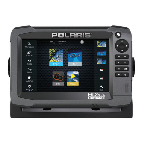
Page 9: Front - Controls
Menu (short press = menu, long press = hide menu bar, double press = Settings menu) Active panel New waypoint (long press = find dialogue) Power key (short press = system controls, long press = power off) Card reader door HDS Gen3 Polaris overview | HDS Gen3 Polaris Installation Manual... -
Page 10: Rear - Connectors
POWER - 12 V input & NMEA 0183. Optional video-in via adaptor SONAR - CHIRP and Broadband Sonar (Feature disabled by default) STRUCTURE - StructureScan HD sonar (Feature disabled by default) HDS Gen3 Polaris overview | HDS Gen3 Polaris Installation Manual... -
Page 11: Microsd Card Slot
(2) from the right hand side. The card reader door should always be shut immediately after inserting or removing a card, in order to prevent possible water and dust ingress. HDS Gen3 Polaris overview | HDS Gen3 Polaris Installation Manual... -
Page 12: Check The Contents
HDS Gen3 Polaris display Suncover Power cable Caps Knobs Documentation pack (Operator & Installation manual, Quick guide, warranty card) Fasteners (4 x 6G x 1.5 panhead PH1) Gimbal bracket 10 | Check the contents | HDS Gen3 Polaris Installation Manual... -
Page 13: Display Installation
Use only 304 or 316 stainless steel fasteners. Mark the screw locations using the bracket as a template, and drill pilot holes. Screw down the bracket. | 11 Display Installation | HDS Gen3 Polaris Installation Manual... - Page 14 The ratchet teeth in the bracket and display case ensure a positive grip and prevent the unit changing from the desired angle. ¼ Note: For mounting in Polaris, vehicle specific dash mount kits, follow the instructions provided. 12 | Display Installation | HDS Gen3 Polaris Installation Manual...
-
Page 15: Wiring
Be sure that the voltage of the power supply is compatible with the HDS Gen3 Polaris display Warning: The HDS Gen3 Polaris has a voltage rating of 12 V DC, it is not suited for use with 24V DC systems. Warning:... -
Page 16: Power Connection
SiriusXM weather receiver. This means that the modules are turned on the moment the display is powered up. For connection, simply combine all yellow wires on a common bus or to a single termination point. 14 | Wiring | HDS Gen3 Polaris Installation Manual... - Page 17 Ethernet is used to connect high bandwidth devices such as Sirius Weather Module. NMEA 2000 device connection HDS Gen3 Polaris models are equiped with a NMEA 2000 connector, which allows the receiving and sharing of a multitude of data from various sources.
- Page 18 12 V DC GPS antenna HDS Gen3 Polaris Display SonicHub ‘Drop’ cables (should not exceed 6m (20’) each) Power cable Micro-C T-connectors Backbone Terminators (one male, one female) 16 | Wiring | HDS Gen3 Polaris Installation Manual...
-
Page 19: Nmea 0183 Device Connection
NMEA 0183 device connection The HDS Gen3 Polaris display has an NMEA 0183 serial port, providing both an input and an output. The port uses the NMEA 0183 (serial balanced) standard, and can be configured in the software for different baud rates up to 38,400 baud. The NMEA 0183 cable shares the same plug as the power cable. -
Page 20: Video In
Video input adaptor cable (optional part, see “Display accessories” on page 34) RCA plug 12 V camera (3rd party. Requires seperate power source) HDS Gen3 Polaris power/data cable ¼ Note: Only connect NTSC and PAL video sources. 18 | Wiring |... -
Page 21: Software Setup
The scrollable left column of icons access most settings that require configuration; First time startup When the HDS Gen3 Polaris is started for the first time, or after restoring factory defaults, the unit will raise prompts requesting the user to select some fundamental setup options. Follow the on- screen instructions. -
Page 22: Source Selection
Configure device Additional device options can be configured from both the Data sources menu or from the Device list, see “Device list” on page 21 for further information. 20 | Software setup | HDS Gen3 Polaris Installation Manual... -
Page 23: Device List
Device list The device list shows the physical and virtual devices that provide data. This may include a module inside the HDS Gen3 Polaris, the NMEA 0183 port, or any external NMEA 2000 device. Selecting a device in this list will bring up additional details and... -
Page 24: Diagnostics
The above information may not always indicate an issue that can be simply resolved with minor adjustment to network layout or connected devices and their activity on the network. However 22 | Software setup | HDS Gen3 Polaris Installation Manual... -
Page 25: Damping
(Tx, Rx) use the same baud rate setting. Serial Output Selection will determine whether the data is output via Tx lines, and will enable editing of the output sentences list. | 23 Software setup | HDS Gen3 Polaris Installation Manual... -
Page 26: Ethernet Setup
No special setup is required for establishing an ethernet network, it is all ‘plug and play’ . An optional NEP-2 connected between the HDS Gen3 Polaris and another network module will automatically start working, and relay data between the two devices. - Page 27 The upper table on the diagnotics page gives an account of the various automatically synchronised databases that ensure all Lowrance displays are using the same user settings and data. Each unit stores the database locally, so that all information is available if the device is run in standalone.
-
Page 28: Wifi Setup
Databases on the upper table. It is preferable to have all UDB versions the same. This can usually be acheived by loading the latest software on to your display - refer to “HDS Gen3 Polaris software upgrades” on page 32. - Page 29 The HDS Gen3 Polaris to which connection is attempted will raise a prompt. Select Yes for one-time connection, or Always if device is to be remembered for regular connection. This setting can be changed later if required. ¼ Note: The HDS Gen3 Polaris internal wireless module only supports GoFree connection to its own display.
- Page 30 DHCP server - only one DHCP server may exist on a network at a time. To set a device as secondary, the HDS Gen3 Polaris must initially be connected to only one WIFI-1 module, which should be set to secondary.
- Page 31 Advanced Tools are available within the HDS Gen3 Polaris software to assist in fault-finding and setting up the wifi network. Iperf Iperf is a commonly used network performance tool.
-
Page 32: Video In Configuration
NMEA 2000 and ethernet devices, with files read off a microSD card. Before initiating an update to the HDS Gen3 Polaris itself, be sure to back up any potentially valuable user data. Backing up and Importing user data... - Page 33 NSS evo2, NSS, NSO, NSE, Zeus, Zeus Touch, HDS Gen2, HDS Gen2 Touch, HDS Gen3). • User data file version 3 (with depth): Use with legacy Lowrance GPS chartplotters • User data file version 2 (no depth): Use with legacy Lowrance GPS chartplotters •...
- Page 34 Importing a database Later, if the HDS Gen3 Polaris has been restored to factory defaults or user data is accidentally deleted, simply return to the files page, highlight the backed up file, and select Import. View file details for creation date.
-
Page 35: Dimensional Drawing
Dimensional drawing HDS-7 Gen3 Polaris 83.7mm (3.3”) 215.4mm (8.48”) 32.3mm (1.27”) 238.4mm (9.39”) 69.2mm (2.72”) 96.5mm (3.8”) | 33 Dimensional drawing | HDS Gen3 Polaris Installation Manual... -
Page 36: Accessories
000-11010-001 HDS GEN2/3 VIDEO ADAPTER CABLE 000-12241-001 HDS-7 TOUCH BEZEL AND CARD DOOR 000-11019-001 HDS-7 TOUCH GIMBAL BRACKET 000-0124-70 HDS CONNECTOR CAPS Other accessories Part Number Description 000-11076-001 WM-3 SIRIUS® WEATHER MODULE 34 | Accessories | HDS Gen3 Polaris Installation Manual... - Page 37 Engine Parameters, Rapid Update 127489 Engine Parameters, Dynamic 127493 Transmission Parameters, Dynamic 127503 AC input status 127504 AC Output Status 127505 Fluid Level 127506 DC Detailed Status 127507 Charger Status | 35 Supported data | HDS Gen3 Polaris Installation Manual...
- Page 38 130313 Humidity 130314 Actual Pressure 130576 Small Craft Status 130577 Direction Data 130840 Data User Group Configuration 130842 SimNet DSC Message 130845 Parameter Handle 130850 Event Command 130851 Event Reply 36 | Supported data | HDS Gen3 Polaris Installation Manual...
- Page 39 Suzuki Engine and Storage Device Config 130832 Fuel Used - High Reolution 130834 Engine and Tank Configuration 130835 SetEngineAndTankConfiguration 130838 Fluid Level Warning 130839 Pressure Insect Configuration 130843 Sonar Status, Frequency and DSP Voltage | 37 Supported data | HDS Gen3 Polaris Installation Manual...
- Page 40 Route and WP Service - WP List - WP Name & Position 130306 Wind Data 130310 Environmental Parameters 130311 Environmental Parameters 130312 Temperature 130577 Direction Data 130840 Data User Group Configuration 130845 Parameter Handle 130850 Event Command 130818 Reprogram Data 38 | Supported data | HDS Gen3 Polaris Installation Manual...
- Page 41 Suzuki Engine and Storage Device Config 130835 SetEngineAndTankConfiguration 130836 Fluid Level Insect Configuration 130837 Fuel Flow Turbine Configuration 130839 Pressure Insect Configuration 130845 Weather and Fish Prediction and Barometric Pressure History 130850 Evinrude Engine Warnings | 39 Supported data | HDS Gen3 Polaris Installation Manual...
- Page 42 BWC BWR RMC RMB XTE XDR Sonar Receive MTW VLW VHW Transmit MTW VLW VHW Compass Receive Transmit HDG Wind Receive MWV MWD Transmit MWV MWD AIS / DSC Receive MARPA Transmit 40 | Supported data | HDS Gen3 Polaris Installation Manual...
-
Page 43: Specifications
4800, 9600, 19200, 38400 baud Video input Composite video RCA - single channel via optional adaptor Data card slot 2x microSD Wireless 802.11b/g/n 10Hz high speed update. GPS & GLONASS. WAAS, MSAS, EGNOS | 41 Specifications | HDS Gen3 Polaris Installation Manual... - Page 44 0980...
Need help?
Do you have a question about the HDS Gen3 Polaris and is the answer not in the manual?
Questions and answers