Table of Contents
Advertisement
Quick Links
User's Manual
UX series :
UX-30A / UX-221A / UX-218A / UX-218RA
Antes de utilizar el equipo, lea la sección
"Precauciones de seguridad" de este manual.
Conserve este manual para futuras consultas.
Before operating the device, please read the
"Safety precautions" section of this manual.
Retain this manual for future reference.
Advertisement
Table of Contents

Related Manuals for DAS UX-221A


Summary of Contents for DAS UX-221A
- Page 1 User's Manual UX series : UX-30A / UX-221A / UX-218A / UX-218RA Antes de utilizar el equipo, lea la sección “Precauciones de seguridad” de este manual. Conserve este manual para futuras consultas. Before operating the device, please read the “Safety precautions” section of this manual.
-
Page 2: Table Of Contents
SAFETY PRECAUTIONS WARRANTY DECLARATION OF CONFORMITY 6 - 7 INTRODUCTION 8 - 9 CONFIGURATIONS Example with UX-218A Example with UX-221A SPECIFICATIONS LINE DRAWINGS AMPLIFIERS 12 - 16 INSTALLATION AND ACCESSORIES 17 - 29 ANNEX I : Unbalanced and balanced connections ANNEX II : DASnet cables Manual del Usuario / UX series / User’s Manual... -
Page 3: Safety Precautions
UX series Precauciones de Seguridad UX-221A / UX-218A / UX-218RA / UX-30A Safety Precautions Cajas acústicas activas / Self-powered loudspeaker enclosures El signo de exclamación dentro de un triángulo indica la The exclamation point inside an equilateral triangle is intend to... -
Page 4: Warranty
GARANTÍA Todos nuestros productos están garantizados por un periodo de 24 meses desde la fecha de compra. Las garantías sólo serán válidas si son por un defecto de fabricación y en ningún caso por un uso incorrecto del producto. reparaciones garantía pueden realizadas,... -
Page 5: Declaration Of Conformity
DECLARACIÓN DE CONFORMIDAD DECLARATION OF CONFORMITY D.A.S. Audio, S.A. C/ Islas Baleares, 24 - 46988 - Pol. Fuente del Jarro - Valencia. España (Spain). UX-221A, UX-218A, UX-218RA UX-30A Declara que UX-221A, UX-218A, UX-218RA UX-30A Declares that Cumple con los objetivos esenciales de las Directivas: Abide by essential objectives relating Directives: Directiva de Baja Tensión (Low Voltage Directive) -
Page 6: Introduction
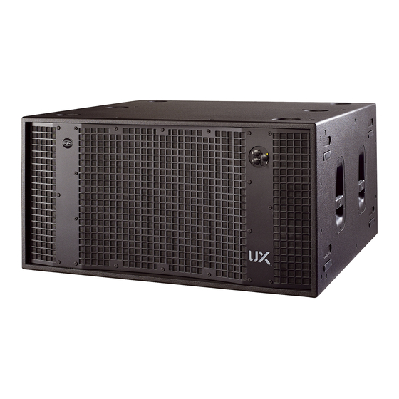
The self-powered UX series is comprised of systems designed in response to demands for high-output ultra-low frequency solutions. UX-30A, UX-218A and UX-221A are self-powered versions of UX series models. In addition, UX-218RA is a version with built-in rigging hardware, and derived model of UX-218A. - Page 7 UX-221A - High power ultra-low frequency subwoofer system - Twin 21" Neodymium loudspeakers with 6" voice coils - Solid 21 mm birch plywood construction - Impressive 60 mm peak-to-peak excursion U X - 2 2 1 A 2 1 U X N...
-
Page 8: Configurations
CONFIGURATIONS Next, find two examples. You will find more configurations on our website. Example with UX-218A: Manual del Usuario / UX series / User’s Manual... -
Page 9: Example With Ux-221A
CONFIGURATIONS (cont’d) Example with UX-221A Manual del Usuario / UX series / User’s Manual... -
Page 10: Specifications
SPECIFICATIONS D.A.S. Audio continuously strives to enhance its products through investigation and development. All specifications are subject to changes without prior notice. Manual del Usuario / UX series / User’s Manual... -
Page 11: Line Drawings
LINE DRAWINGS ALL DIMENSIONS IN MILLIMETERS UX-221A UX-218A UX-218RA UX-30A Manual del Usuario / UX series / User’s Manual... -
Page 12: Amplifiers
AMPLIFIERS DESCRIPTION 1) SIGNAL INPUT : XLR type input signal connectors. As the LOOP THRU connector, they are balanced with the following pin assignments: 1=GND (Ground). 2=(+) Non inverted input. 3=(-) Inverted input. 2) LOOP THRU : XLR type output signal connector for connecting several units together and sending them all the same input signal. - Page 13 8) IN/OUT : Neutrik EtherCon connectors for audio+data input/output with DASnet . With the output connector we can interconnect several units. 9) Zone for user notes. 10) AC INPUT SELECT : This switch actives, or not, the mains connector at the front side of the enclosure. When we use a cardioid configuration, we should connect the mains at the front side of the turned enclosure for wires' grouping.
- Page 14 In the next figure, we can view this menu of the Overload indicator UX-221A units. This device has a SIGNAL/LIMIT indicator. The red light indicates the signal is excessive. The indicator should not be lit continuously.
- Page 15 As example of available low pass filters we will to control and adjust the phase of the subs is view the UX-221A units case, with 4 cut available recommended (with a digital processor, for frequencies: 50, 63, 80 and 100 Hz (see the example).
- Page 16 Troubleshooting PROBLEM CAUSE SOLUTION sound from unit. 1 – The signal source is sending no 1 – Check that the mixer or sound SIGNAL LED does not light up. signal. source is sending signal to the UNIT. 2 – Defective cable. 2 –...
-
Page 17: Installation And Accessories
Enclosure 2 eCP_20 With UX-221A units, select FRONT with this switch to enable the mains connector at the front side of the turned enclosure (enclosure 1), while select REAR for the enclosure 2. The only case in which this way of connecting the units will not be possible is when the cardioid configuration is made with UX-30A units, since these lack front connectors. - Page 18 ACCESSORIES To perform any operations related to flying the system, read the present document first, and act on the warnings and advice given. The goal is to the allow the user to become familiar with the mechanical elements required to fly the acoustic system, as well as the safety measures to be taken during set-up and teardown.
- Page 19 Even though it features integrated rigging points for threaded eyebolts (ANL-2), the most practical use of UX-221A is stacked. Using the PL-221S dolly platform (WLL = 450 kg), we can stack and transport up to three UX-221A units; and care should be taken to avoid roll over when moving them, preventing injuries.
- Page 20 PL-UX218RS PL-UX218S PL-30S Also a dolly platform is available for transporting and stacking UX-30A units (PL-30S, with WLL = 250 kg). Using this dolly platform we can stack and transport up to two units; and care should be taken to avoid roll over when moving them.
- Page 21 RIGGING Out of the subwoofers in this manual, only UX-218RA can use a frame designed specifically for flying. UX- 218A can be converted to UX-218RA by means of the KITR-UX218 accessory kit. Only in this way will the enclosure be safely suspended. Note: when handling heavy loads, always wear appropriate clothing and protective elements such as gloves, safety shoes, etc.
- Page 22 Unless it has already been done, place the enclosure on top of a PL- UX218RS platform. Note: Bear in mind that the unit is not attached to the platform via quick release pins like other models. It is in these preparation steps that you need to take into account which units go forward and which ones go backwards in cardioid...
- Page 23 Expose the upper guides of the units like we previously did with the lower unit. Place the side parts of the AX- UX218, each on its correct side (check the silk screening), lining up holes of the quick release pins, as shown.
- Page 24 Attach the pick-up point, or pick-up points, to the holes in the side of the AX parts indicated by Ease Focus, using the quick release pins. Remember that one pick-up bar only provides a single pick-up point. If another pick-up point is required, an additional pick-up bar is needed.
- Page 25 Lift the assembly slightly and remove the dolly platform so as to be able to add Aero 40A enclosures. To prepare groups of 4 Aero 40A units on PL-40S platforms, and select inter-box angles, consult the rigging manual for Aero 40A, RM_AERO40, which can be found on our website.
- Page 26 Expose the guides in the upper Aero 40A. Once the guides are prepared and aligned, link the two groups together using quick release pins. Observe the indications present in the silkscreen lettering and use the Aero 40A rigging manual, RM_AERO40, additional information.
- Page 27 Once the two groups have been joined together, you can start selecting angles for Aero 40A units according to the angles indicated by Ease Focus software, and according to the indications in the Aero 40A rigging manual, RM_AERO40. Remember that inter-box angles between Aero 40A units have been 0º, so...
- Page 28 Lift the assembly slightly and remove the PL-40S dolly platform. Next, lift the assembly so as to leave room for the second group of Aero 40A (as stated, our example will use a total of 8 Aero 40A). For the second group, proceed as with the first group, setting enclosure angles before removing the platform.
- Page 29 The final result can be seen in the attached figure. disassembly transport, it is again advisable that you go through the Aero 4 0 A r i g g i n g m a n u a l , RM_AERO40, that can be found on our website.
-
Page 30: Annex I : Unbalanced And Balanced Connections
ANNEX I : Unbalanced and balanced connections There are two basic ways to transport an audio signal with microphone or line level: Unbalanced line: Utilising a two conductor cable, it transports the signal as the voltage between them. Electromagnetic interference can get added to the signal as undesired noise. Connectors that carry unbalanced signals have two pins, such as RCA (Phono) and ¼”... -
Page 31: Annex Ii : Dasnet Cables
ANNEX II : DASnet cables With each system, cabling and patch panels are provided. It is very important to use the system with the intended cables to prevent electromagnetic interferences between the analog audio signal, the DASnet data and the power. Be sure to check the specifications provided by the cable manufacturer. - Page 32 C/. Islas Baleares, 24 6900 NW 52th Street 3 Temasek Avenue, Centennial Tower #34-36 46988 Fuente del Jarro Miami, FL. 33166 - U.S.A. Singapore 039190 Valencia, SPAIN TOLL FREE: 1 888 DAS 4 USA Tel. +65 6549 7760 Tel. +34 96 134 0860...
Need help?
Do you have a question about the UX-221A and is the answer not in the manual?
Questions and answers