Table of Contents
Advertisement
Quick Links
AssuredSAN Ultra48 Series
Setup Guide
Abstract
This document describes initial hardware setup for Dot Hill AssuredSAN Ultra48 Series controller enclosures, and is intended for use
by storage system administrators familiar with servers and computer networks, network administration, storage system installation
and configuration, storage area network management, and relevant protocols.
P/N 83-00006723- 1 0-01
Revision A
April 2014
Advertisement
Table of Contents
Troubleshooting

Subscribe to Our Youtube Channel
Related Manuals for Dot Hill Systems AssuredSAN 4844

Summary of Contents for Dot Hill Systems AssuredSAN 4844
- Page 1 AssuredSAN Ultra48 Series Setup Guide Abstract This document describes initial hardware setup for Dot Hill AssuredSAN Ultra48 Series controller enclosures, and is intended for use by storage system administrators familiar with servers and computer networks, network administration, storage system installation and configuration, storage area network management, and relevant protocols.
- Page 2 Copyright © 2014 Dot Hill Systems Corp. All rights reserved. Dot Hill Systems Corp., Dot Hill, the Dot Hill logo, AssuredSAN, AssuredSnap, AssuredCopy, AssuredRemote, R/Evolution, and the R/Evolution logo are trademarks of Dot Hill Systems Corp. All other trademarks and registered trademarks are proprietary to their respective owners.
-
Page 3: Table Of Contents
Contents About this guide ............11 Overview. - Page 4 Fibre Channel host connection ..........35 10GbE iSCSI host connection.
- Page 5 Host-side connection troubleshooting featuring SAS host ports ......62 Isolating a controller module expansion port connection fault ....... . . 63 Isolating AssuredRemote replication faults .
- Page 6 Device driver/special operation mode ..........92 Microsoft Windows .
- Page 7 Figures 1 2U48 enclosure: front panel with bezel installed ........15 2 2U48 enclosure: front panel with bezel removed .
- Page 8 Figures...
- Page 9 Tables 1 Related documents ............12 2 Document conventions .
- Page 10 Tables...
-
Page 11: About This Guide
CNC ports used for host connection AssuredSAN 4844 models use Converged Network Controller (CNC) technology, allowing you to select the desired host interface protocol from the available Fibre Channel (FC) or Internet SCSI (iSCSI) host interface protocols supported by the system. You can use the Command-line Interface (CLI) to set all controller module CNC ports to use one of these host interface protocols: •... -
Page 12: Hd Mini-Sas Ports Used For Host Connection
HD mini-SAS ports used for host connection AssuredSAN 4544 models provide four high-density mini-SAS (HD mini-SAS) ports per controller module. The HD mini-SAS host interface protocol uses the SFF-8644 external connector interface defined for SAS3.0 to support a link rate of 12 Gbit/s using the qualified connectors and cable options. See 4544 SAS controller module—rear panel LEDs on page 80 for more information. -
Page 13: Document Conventions And Symbols
Document conventions and symbols Table 2 Document conventions Convention Element Blue text Cross-reference links and e-mail addresses Blue, underlined text Web site addresses Bold text • Key names • Text typed into a GUI element, such as into a box •... - Page 14 About this guide...
-
Page 15: Components
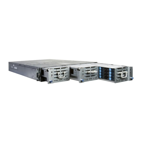
Components Front panel components AssuredSAN Ultra48 Series supports 2U48 enclosures. The 2U48 chassis—configured with up to 48 2.5" small form factor (SFF) disks—is used as either a controller enclosure or expansion enclosure. Supported expansion enclosures are used for adding storage. The 4144 is the high-capacity 2U48 drive enclosure used for adding storage. -
Page 16: Enclosure Bezel Removed
Enclosure bezel removed To access the drawers, you must remove the enclosure bezel (shown removed in Figure Right ear Left ear Note: Integers atop drawers indicate drawer numbering sequence. (Silk screens on bezel) 1 Enclosure ear LEDs (see Figure 1 on page 15) 5 Drawer status LED: FRU OK 2 Thumbscrew for securing or accessing drawer... -
Page 17: Disk Drives Used In Ultra48 Series Enclosures
IMPORTANT: Disk drive slot numbering is also provided on the label that is laminated to the sheet metal housing (top face) on each drawer. Refer to the drawer label when installing disks into the drawer. Figure 4 below provides a sample partial configuration of disk bays within a drawer. The bay on the left is populated with four disks, whereas the adjacent bay on the right contains an AMS insert to manage air flow within the enclosure to maintain optimal operating temperature. -
Page 18: Controller Enclosure - Rear Panel Layout
Controller enclosure — rear panel layout The diagram and table below display and identify important component items that comprise the rear panel layout of an AssuredSAN Ultra48 Series controller enclosure. The 4844 is shown as a representative example of 2U48 controller enclosure models included in the product series. 6Gb/s PORT 0 PORT 1... -
Page 19: 4844 Controller Module - Rear Panel Components
4844 controller module — rear panel components Figure 6 shows CNC ports configured with SFPs supporting either 4/8/16 Gb FC or 10GbE iSCSI. The SFPs look identical. Refer to the CNC LEDs that apply to the specific configuration of your CNC ports. 6Gb/s PORT 0 PORT 1... -
Page 20: 4544 Controller Module - Rear Panel Components
4544 controller module — rear panel components Figure 8 shows host ports configured with 12 Gbit/s HD mini-SAS (SFF-8644) connectors. LINK LINK LINK LINK 12Gb/s 12Gb/s 6Gb/s SAS 0 SAS 1 SAS 2 SAS 3 CACHE SERVICE−2 LINK SERVICE−1 1 HD mini-SAS ports used for host connection 6 Service port 1 (used by service personnel only) 2 CLI port (USB - Type B) [see Appendix D] 7 Disabled button (used by engineering only) -
Page 21: Cache
• Replacing a power supply unit with integrated cooling fans. • Replacing ear components • Replacing a Fibre Channel transceiver • Replacing a 10GbE SFP+ transceiver • Replacing a 1 Gb SFP transceiver • Replacing a controller enclosure chassis See Dot Hill’s Customer Resource Center web site for additional information: http://crc.dothill.com. Select AssuredSAN &... -
Page 22: Supercapacitor Pack
Controller module pictorial (Midplane-facing rear view) Host interface USB - Type A (shown covered) CompactFlash card Figure 10 CompactFlash card Supercapacitor pack To protect controller module cache in case of power failure, each controller enclosure model is equipped with supercapacitor technology, in conjunction with CompactFlash memory, built into each controller module to provide extended cache memory backup time. -
Page 23: Installing The Enclosures
Installing the enclosures Installation checklist The following table outlines the steps required to install the enclosures, and initially configure and provision the storage system. To ensure successful installation, perform the tasks in the order presented. Table 3 Installation checklist Step Task Where to find procedure Install the controller enclosure and optional See the rack-mount bracket kit installation instructions... -
Page 24: Populating Drawers
Populating drawers Although the 2U48 chassis provides pre-assembled and pre-installed drawer FRUs (drawers), disk drive modules must be installed into the drawers. In addition to locating your disk modules—and any Air Management Solution (AMS) inserts, you should become familiar with the following concepts before populating the drawers: •... -
Page 25: Aligning An Ams Or Disk Module For Installation Into A Drawer
Figure 13 Opening and closing a drawer: pull or push drawer along slide To close the drawer, simply slide the drawer into the enclosure along the drawer slide until it properly seats in the drawer bay. Take care to ensure there are no loose cable wires protruding beyond the limits of the igus chainflex cable. -
Page 26: Installing An Ams
Installing an AMS Refer to Figure 15 when orienting the AMS for insertion into the target drawer. If you are installing into the left drawer or middle drawer, refer to the illustration on the left when performing this step-procedure. If you are installing into the right drawer, refer to the illustration on the right when performing this step-procedure. -
Page 27: Fde Considerations
Align SFF 2.5" disk module for insertion into drive slot Left or middle drawer Right drawer Figure 17 Orient the disk for installation 1. While supporting the bottom of the disk module with one hand (disk PCBA should be facing up and latch release flanges should be facing out)—align the disk for insertion into the target disk slot. -
Page 28: Connecting The Controller Enclosure And Drive Enclosures
While replacing or installing FDE-capable disk drive modules, consider the following: • If you are installing FDE-capable disk drive modules that do not have keys into a secure system, the system will automatically secure the disks after installation. Your system will associate its existing key with the disks, and you can transparently use the newly-secured disks. -
Page 29: Connecting The Ultra48 Series Controller To The 4144 Drive Enclosure
Connecting the Ultra48 Series controller to the 4144 drive enclosure The high capacity 4144 48-drive enclosure, supporting 6 Gb internal disk drive and expander link speeds, can be attached to a Ultra48 Series controller enclosure using supported mini-SAS to mini-SAS cables of 0.5 m (1.64') to 2 m (6.56') length (see Figure 19 on page 30). -
Page 30: Cabling Connections Between A Controller Enclosure And One Drive Enclosure
Controller A Controller enclosure Controller B Drive enclosure Figure 19 Cabling connections between a controller enclosure and one drive enclosure The figure above provides an example of an Ultra48 Series controller enclosure cabled to a single drive enclosure. The illustration shows cabling of enclosures equipped with dual IOMs. See the “Replacing a controller or expansion module”... -
Page 31: Testing Enclosure Connections
Refer to these diagrams when cabling multiple compatible drive enclosures together with the Ultra48 Series controller enclosure. Testing enclosure connections Power cycling procedures vary according to the type of power supply unit (PSU) provided with the enclosure. Some compatible enclosure models are equipped with PSUs that do not have power switches; whereas Ultra48 Series enclosures use a PSU model that is equipped with a power switch. -
Page 32: Connect Power Cord To Ac Power Supply
Connect power cord to AC power supply Power supply module Rack power source Figure 22 AC power cord Obtain two suitable AC power cords: one for each AC power supply that will connect to a separate power source. See Figure 22 on page 32 and the illustration at left in Figure 21 when performing the following... -
Page 33: Connecting Hosts
Configuring host ports). CNC technology AssuredSAN 4844 models use Converged Network Controller technology, allowing you to select the desired host interface protocol(s) from the available FC or iSCSI host interface protocols supported by the system. The small form-factor pluggable (SFP transceiver or SFP) connectors used in CNC ports are further described in the subsections below. -
Page 34: Fibre Channel Protocol
IMPORTANT: Use the set host-port-mode CLI command to set the host interface protocol for CNC ports using qualified SFP options. AssuredSAN 4844 models ship with CNC ports configured for FC. When connecting CNC ports to iSCSI hosts, you must use the CLI (not RAIDar) to specify which ports will use iSCSI. -
Page 35: Gb Iscsi Protocol
Ethernet, iSCSI, and optionally, multipath I/O. 1 Gb iSCSI protocol AssuredSAN 4844 controller enclosures support two controller modules using the Internet SCSI interface protocol for host port connection. Each controller module provides four iSCSI host ports configured with an RJ-45 SFP supporting data rates up to 1 Gbit/s, using either one-way or mutual CHAP. -
Page 36: Gb Iscsi Host Connection
10GbE iSCSI host connection To connect 4844 controller modules supporting 10GbE iSCSI host interface ports to a server HBA or switch—using the controller’s CNC ports—select a qualified 10GbE SFP option. Qualified options support cable lengths of 0.5 m (1.64'), 1 m (3.28'), 3 m (9.84'), 5 m (16.40'), and 7 m (22.97') for copper cables;... -
Page 37: Connecting Hosts: Direct Attach-One Server/One Hba/Dual Path
One server/one HBA/dual path 4844 Server 6Gb/s 6Gb/s 4544 12Gb/s 12Gb/s Server 6Gb/s 12Gb/s 12Gb/s 6Gb/s Figure 23 Connecting hosts: direct attach—one server/one HBA/dual path Two servers/one HBA per server/dual path 4844 Server 1 Server 1 Server 2 6Gb/s 6Gb/s 4544 Server 1 Server 1... -
Page 38: Connecting Switch Attach Configurations
4544 Server 1 Server 2 Server 3 Server 4 12Gb/s 12Gb/s 6Gb/s 12Gb/s 12Gb/s 6Gb/s Figure 26 Connecting hosts: direct attach—four servers/one HBA per server/dual path Connecting switch attach configurations A switch attach solution—or SAN—places a switch between the servers and the controller enclosures within the storage system. -
Page 39: Connecting Hosts: Switch Attach-Four Servers/Multiple Switches/San Fabric
Four servers/multiple switches/SAN fabric 4844 6Gb/s 6Gb/s Server 1 Server 2 Server 3 Server 4 Figure 28 Connecting hosts: switch attach—four servers/multiple switches/SAN fabric Ultra48 Series controller enclosure iSCSI considerations When installing an Ultra48 Series iSCSI controller enclosure, use at least three ports per server—two for the storage LAN, and one or more for the public LAN(s)—to ensure that the storage network is isolated from the other networks. -
Page 40: Connecting A Management Host On The Network
• Controller A port 3: 10.1 1.10.130 • Controller B port 0: 10.10.10.140 • Controller B port 1: 10.1 1.10.150 • Controller B port 2: 10.10.10.160 • Controller B port 3: 10.1 1.10.170 In addition to setting the port-specific options described above, you can also set common options. In RAIDar‘s Configuration View panel, right-click the system and select Configuration >... -
Page 41: Cabling For Replication
• Be sure of the desired link type before creating the replication set, because you cannot change the replication link type after creating the replication set. • For the sake of system security, do not unnecessarily expose the controller module network port to an external network connection. -
Page 42: Dual-Controller Configuration
Dual-controller configuration Each of the following diagrams show the rear panel of two 4844 controller enclosures equipped with dual-controller modules. The controller modules can use qualified SFP options of the same type, or they can use a combination of qualified SFP options supporting different interface protocols. Multiple servers/single network The diagram below shows the rear panel of two 4844 controller enclosures with both I/O and replication occurring on the same physical network. -
Page 43: Connecting Two Storage Systems For Assuredremote: Multiple Servers/Switches/Two Locations
Multiple servers/different networks/multiple switches The diagram below shows the rear panel of two 4844 controller enclosures with I/O and replication occurring on different networks. Peer sites with failover 4844 controller enclosure 4844 controller enclosure 6Gb/s 6Gb/s 6Gb/s 6Gb/s I/O switch Ethernet To host servers To host servers... -
Page 44: Connecting Two Storage Systems For Assuredremote: Multiple Servers/San Fabric/Two Locations
Remote site “B” Remote site “A” Peer sites with failover Corporate Corporate end-users end-users Ethernet 4844 storage system (typ. 2 places) 6Gb/s 6Gb/s 6Gb/s 6Gb/s App “A” FS “A” App “A” FS “A” data data replica replica FS “B” App “B” App “B”... -
Page 45: Updating Firmware
Updating firmware After installing the hardware and powering on the storage system components for the first time, verify that the controller modules, expansion modules, and disk drives are using the current firmware release. Using RAIDar, right-click the system in the Configuration View panel, and select Tools > Update Firmware. The Update Firmware panel displays the currently installed firmware versions, and allows you to update them. -
Page 46: Terminal Emulator Display Settings
Once new IP addresses are set, you can change them as needed using RAIDar. Be sure to change the IP address via RAIDar before changing the network configuration. See Accessing RAIDar on page 51 for more information concerning the web-based storage management application. 1. - Page 47 5. In the terminal emulator, connect to controller A. 6. Press Enter to display the CLI prompt (#). The CLI displays the system version, MC version, and login prompt: a. At the login prompt, enter the default user manage b. Enter the default password !manage If the default user or password—or both—have been changed for security reasons, enter the secure login credentials instead of the defaults shown above.
-
Page 48: Change The Cnc Port Mode
NOTE: Using HyperTerminal with the CLI on a Microsoft Windows host: On a host computer connected to a controller module’s mini-USB CLI port, incorrect command syntax in a HyperTerminal session can cause the CLI to hang. To avoid this problem, use correct syntax, use a different terminal emulator, or connect to the CLI using telnet rather than the mini-USB cable. - Page 49 After changing the CNC port mode, you can invoke RAIDar and use the Configuration Wizard to initially configure the system, or change system configuration settings as described in the AssuredSAN 4004 Series RAIDar User Guide and Basic operation. AssuredSAN Ultra48 Series Setup Guide...
- Page 50 Connecting hosts...
-
Page 51: Basic Operation
Basic operation Verify that you have successfully completed the sequential “Installation Checklist” instructions in Table 3 page 23. Once you have successfully completed steps 1 through 8 therein, you can access the management interfaces using your web-browser, to complete the system setup. Accessing RAIDar Upon completing the hardware installation, you can access the controller module’s web-based management interface, RAIDar, to configure, monitor, and manage the storage system. - Page 52 Basic operation...
-
Page 53: Troubleshooting
Troubleshooting USB CLI port connection AssuredSAN Ultra48 Series controllers feature a CLI port employing a mini-USB Type B form factor. If you encounter problems communicating with the port after cabling your computer to the USB device, you may need to either download a device driver (Windows), or set appropriate parameters via an operating system command (Linux). -
Page 54: Use The Cli
find each component that has a problem, and follow actions in the component Health Recommendations field to resolve the problem. Use the CLI As an alternative to using RAIDar, you can run the command in the CLI to view the health of show system the system and its components. -
Page 55: Isolate The Fault
• Error. A failure occurred that may affect data integrity or system stability. Correct the problem as soon as possible. • Warning. A problem occurred that may affect system stability, but not data integrity. Evaluate the problem and correct it if necessary. •... -
Page 56: Diagnostic Steps
IMPORTANT: Stopping I/O to a vdisk is a host-side task, and falls outside the scope of this document. When on-site, you can verify that there is no I/O activity by briefly monitoring the system LEDs; however, when accessing the storage system remotely, this is not possible. Remotely, you can use the show command to determine if input and output has stopped. -
Page 57: Is The Controller Back Panel Fru Ok Led Off
Is the controller back panel FRU OK LED off? Answer Possible reasons Actions System functioning properly. No action required. (blinking) System is booting. Wait for system to boot. The controller module is not powered on. • Check that the controller module is fully inserted The controller module has failed. -
Page 58: Is The Disk Drive Module Led Off
Is the disk drive module LED off? Answer Possible reasons Actions • There is no power. Check that the disk drive module is fully inserted and latched in place, and that both the enclosure and the • The disk drive is offline. drawer are powered on. -
Page 59: Is A Connected Port Expansion Port Status Led Off
Is a connected port Expansion Port Status LED off? Answer Possible reasons Actions System functioning properly. No action required. The link is down. • Check cable connections and reseat if necessary. • Inspect cable for damage. Replace cable if necessary. •... -
Page 60: Controller Failure In A Single-Controller Configuration
Controller failure in a single-controller configuration This subsection addresses a potential situation that might occur if a partner controller fails following failure of its peer controller. IMPORTANT: The Ultra48 Series enclosures support dual-controller environments only. Do not transport the CompactFlash since data corruption might occur. Single-controller support is provided only when a controller fails over to its partner controller. -
Page 61: Isolating A Host-Side Connection Fault
Isolating a host-side connection fault During normal operation, when a controller module host port is connected to a data host, the port’s host link status/link activity LED is green. If there is I/O activity, the host activity LED blinks green. If data hosts are having trouble accessing the storage system, and you cannot locate a specific fault or cannot access the event logs, use the applicable procedure that follows. -
Page 62: Host-Side Connection Troubleshooting Featuring Sas Host Ports
9. Verify that the switch, if any, is operating properly. If possible, test with another port. 10. Verify that the HBA is fully seated, and that the PCI slot is powered on and operational. 1 1. Replace the HBA with a known good HBA, or move the host side cable and SFP to a known good HBA. -
Page 63: Isolating A Controller Module Expansion Port Connection Fault
Isolating a controller module expansion port connection fault During normal operation, when a controller module’s expansion port is connected to a drive enclosure, the expansion port status LED is green. If the connected port’s expansion port LED is off, the link is down. Use the following procedure to isolate the fault. -
Page 64: Isolating Assuredremote Replication Faults
Isolating AssuredRemote replication faults Cabling for replication AssuredRemote replication is a licensed feature for disaster-recovery. This feature performs asynchronous (batch) replication of block-level data from a volume on a local storage system to a volume that can be on the same system, or a second, independent system. The second system can be located at the same site as the first system, or at a different site. -
Page 65: Can You View Information About Remote Links
Answer Possible reasons Actions Compatible firmware revision Perform the following actions on each system used for supporting AssuredRemote is not replication: running on each system used for • In the Configuration View panel in RAIDar, right-click the replication. system, and select Tools > Update Firmware. The Update Firmware panel displays currently installed firmware versions. -
Page 66: Can You Replicate A Volume
Answer Possible reasons Actions Unable to select the replication mode • In RAIDar, review event logs for indicators of a specific fault (Local or Remote)? in a host or replication data path component. Follow any Recommended Actions. • Local Replication mode replicates to a secondary volume residing in the local storage system. -
Page 67: Can You View A Replication Image
Answer Possible reasons Actions Network error occurred during • In RAIDar, review event logs for indicators of a specific fault in-progress replication. in a replication data path component. Follow any Recommended Actions. • In the Configuration View panel in RAIDar, right-click the secondary volume, and select View >... -
Page 68: Sensor Locations
If you need to replace a module, leave the old module in place until you have the replacement or use a blank module to fill the slot. Leaving a slot open negatively affects the airflow and can cause the enclosure to overheat. 4. -
Page 69: Power Supply Module Voltage Sensors
Table 26 Controller module temperature sensor descriptions Description Normal operating Warning operating Critical operating Shutdown values range range range CPU temperature 3°C–88°C 0°C–3°C, > 90°C 0°C 88°C–90°C 100°C FPGA temperature 3°C–97°C 0°C–3°C, None 0°C 97°C–100°C 105°C Onboard temperature 1 0°C–70°C None None None... - Page 70 Troubleshooting...
-
Page 71: Aled Descriptions
LED descriptions Front panel LEDs AssuredSAN Ultra48 Series supports high-capacity 2U48 enclosures. The 2U48 chassis—configured with 48 2.5" small form factor (SFF) disks—is used as either a controller enclosure or expansion enclosure. The 4144 2U48 48-drive enclosure is used for adding storage. Enclosure bezel Each AssuredSAN Ultra48 Series enclosure is equipped with a removable bezel designed to cover the front panel during enclosure operation. -
Page 72: Partial Assembly Showing Bezel Alignment With 2U48 Chassis
Ball stud on chassis ear (typical 4 places) Enclosure bezel sub-assembly (Includes EMI shield for disks) Pocket opening (typical 2 places) Figure 35 Partial assembly showing bezel alignment with 2U48 chassis Once you have removed the bezel, you can access the drawers. To open a drawer, you should first revolve the pull-handle upwards by 90°... -
Page 73: 48-Drive Enclosure Front Panel Leds
48-drive enclosure front panel LEDs Enclosure front panel LEDs are described in two interrelated figure/table ensembles within this subsection: • Figure 37: describes enclosure front panel LEDs (visible with the bezel installed). • Figure 38 on page 74: describes drawer panel LEDs (visible with the bezel removed). The disk module LED is described in another related figure/table ensemble within Disk drive LED:... -
Page 74: Leds Visible With Enclosure Bezel Removed
LEDs visible with enclosure bezel removed The enclosure bezel is removed to reveal the underlying 2U48 enclosure front panel LEDs. The front panel LEDs—including ear LEDs and drawer panel LEDs—are described in the table below the illustration. Right ear Left ear Note: Integers atop drawers indicate drawer numbering sequence. -
Page 75: Disk Drive Led
Disk drive LED You must remove the enclosure bezel to facilitate visual observation of the drawers containing disk drive modules. To view disks in a drawer, you must open the drawer (see see Opening and closing a drawer page 24). Alternatively, you can use management interfaces to monitor disk LED behavior. Disk aligned for Drawer 0 or 1 Disk aligned for Drawer 2 Bi-color LED... - Page 76 Table 29 LEDs: Disks in 2U48 enclosures Disk drive module LED behavior SFF disk drive module State Color Action Description Disk drive OK, None None FTOL On (operating normally) Green OK to remove Blue Identifying self—offline/online Blue Blink—1Hz Disk drive I/O Initializing Green Blink...
-
Page 77: Controller Enclosure - Rear Panel Layout
Controller enclosure — rear panel layout The diagram and table below display and identify important component items that comprise the rear panel layout of an AssuredSAN Ultra48 Series controller enclosure. In Figure 40 below, a 4844 is shown as a representative example. -
Page 78: 4844 Cnc Controller Module - Rear Panel Leds
4844 CNC controller module — rear panel LEDs 6Gb/s PORT 0 PORT 1 PORT 2 PORT 3 CACHE LINK SERVICE−2 SERVICE−1 = FC LEDs = iSCSI LEDs Description Definition Host 4/8/16 Gb FC Off — No link detected. Link Status/ Green —... -
Page 79: Leds: 4844 Cnc Controller Module (1 Gb Rj-45 Sfps)
NOTE: For information about supported combinations of host interface protocols using CNC ports, see ports used for host connection on page 1 1 and the “Configuring host ports topic” in the RAIDar User Guide. 6Gb/s PORT 0 PORT 1 PORT 2 PORT 3 CACHE SERVICE−2... -
Page 80: 4544 Sas Controller Module-Rear Panel Leds
4544 SAS controller module—rear panel LEDs LINK LINK LINK LINK 12Gb/s 12Gb/s 6Gb/s SAS 0 SAS 1 SAS 2 SAS 3 CACHE SERVICE−2 LINK SERVICE−1 Description Definition Host 12 Gb SAS, Off — No link detected. Link Status Green — The port is connected and the link is up. Host 12 Gb SAS Off —... -
Page 81: Power Supply Leds
When a controller is shut down or otherwise rendered inactive—its Link Status LED remains illuminated— falsely indicating that the controller can communicate with the host. Though a link exists between the host and the chip on the controller, the controller is not communicating with the chip. To reset the LED, the controller must be power-cycled (see Powering on/powering off on page 31... -
Page 82: 4144 Drive Enclosure Rear Panel Leds
NOTE: See Powering on/powering off for information on power-cycling enclosures. on page 31 4144 drive enclosure rear panel LEDs The rear panel layout of the 4144 drive enclosure is shown below. Using mini-SAS (SFF-8088) external connectors, this drive enclosure supports a 6-Gbps data rate for backend SAS expansion. See Powering on/powering off for more information. -
Page 83: B Environmental Requirements And Specifications
Environmental requirements and specifications Safety requirements Install the system in accordance with the local safety codes and regulations at the facility site. Follow all cautions and instructions marked on the equipment. IMPORTANT: Also see the hard copy AssuredSAN Product Regulatory Compliance and Safety document (included in your product ship kit). -
Page 84: Weight And Placement Guidelines
Weight and placement guidelines Refer to Physical requirements on page 85 for detailed size and weight specifications. • The weight of an enclosure depends on the number and type of modules installed. • Use two people to lift an enclosure. You can reduce the weight by removing the power supply modules and enclosure drawers. -
Page 85: Physical Requirements
Physical requirements The floor space at the installation site must be strong enough to support the combined weight of the rack, controller enclosures, drive enclosures, and any additional equipment. The site also requires sufficient space for installation, operation, and servicing of the enclosures, together with sufficient ventilation to allow a free flow of air to all enclosures. -
Page 86: Rackmount Enclosure Dimensions
Note: For clarity, only key view projection lines are shown. Key for generic enclosure diagram: − Enclosure front view without bezel or disks − Enclosure bezel top view (reference only) − Enclosure top view (section removed) − Enclosure bezel side view (reference only) −... -
Page 87: Environmental Requirements
NOTE: The table below provides comparative information about optional drive enclosures used with 4004 Series controller enclosures. Ultra48 Series controller enclosures optionally use 4144 drive enclosures. Table 33 Rackmount compatible drive enclosure weights (ordered separately) Specifications Rackmount 4124 (SFF 2.5" 24-drive enclosure) 8.6 kg (19.0 lb) [chassis] •... -
Page 88: Electrical Requirements
Electrical requirements Site wiring and power requirements Each enclosure has two power supply modules for redundancy. If full redundancy is required, use a separate power source for each module. The AC power supply unit in each power supply module is auto-ranging and is automatically configured to an input voltage range from 88–264 VAC with an input frequency of 47–63 Hz. -
Page 89: C Electrostatic Discharge
Electrostatic discharge Preventing electrostatic discharge To prevent damaging the system, be aware of the precautions you need to follow when setting up the system or handling parts. A discharge of static electricity from a finger or other conductor may damage system boards or other static-sensitive devices. - Page 90 Electrostatic discharge...
-
Page 91: Dusb Device Connection
USB device connection Rear panel USB ports AssuredSAN Ultra48 Series controllers contain two different USB (universal serial bus) management interfaces: a Host interface and a Device interface. Both interfaces pertain to the Management Controller (MC). The Device interface is accessed via a port on the controller module face plate. The Host interface (USB Type A)—reserved for future use—is accessible from the midplane-facing end of the controller module (see Figure 10... -
Page 92: Supported Host Applications
Supported host applications Ultra48 Series controllers support the following applications to facilitate connection. Table 36 Supported terminal emulator applications Application Operating system HyperTerminal and TeraTerm Microsoft Windows (all versions) Minicom Linux (all versions) Solaris HP-UX Command-line Interface Once the management computer detects connection to the USB-capable device, the Management Controller awaits input of characters from the host computer via the command-line. -
Page 93: Linux
Linux Although Linux operating systems do not require installation of a device driver, certain parameters must be provided during driver loading to enable recognition of the AssuredSAN Ultra48 Series controller enclosures. Setting parameters for the device driver 1. Enter the following command: modprobe usbserial vendor=0x210c product=0xa4a7 use_acm=1 2. - Page 94 USB device connection...
-
Page 95: Esfp Option For Cnc Ports
SFP option for CNC ports Locate the SFP transceivers Locate the qualified SFP option for your CNC controller module within your product ship kit. The SFP transceiver (SFP) should look similar to the generic SFP shown in the figure below. Follow the guidelines provided in Electrostatic discharge when installing an SFP. - Page 96 SFP option for CNC ports...
-
Page 97: Index
Index Numerics network port service port 1 2U12 service port 2 3.5" 12-drive enclosure 4844 rear panel 2U24 CLI (reserved for future use) 2.5" 24-drive enclosure CLI port (USB) 2U48 CNC ports (1 Gb iSCSI) 2.5" 48-drive enclosure CNC ports (FC/10GbE) expansion port network port accessing... - Page 98 initial configuration SAS In Port Status input frequency requirement SAS Out Port Status input voltage requirement Unit Locator installation checklist Disk site requirements Power/Activity troubleshooting Removal/ID/Fault weight enclosure rear panel Ethernet cables 4544 requirements 12 Gb Host Link Activity 12 Gb Host Link Status Cache Status Expansion Port Status faults...
- Page 99 RFI/EMI connector hoods warnings temperature voltage safety precautions web site sensors Dot Hill Systems Customer Resource Center locating power supply temperature voltage SFP transceivers installing locating supported options verifying operation shock non-operating range...
- Page 100 100 Index...
Need help?
Do you have a question about the AssuredSAN 4844 and is the answer not in the manual?
Questions and answers