Table of Contents
Advertisement
Quick Links
I
n
s
t
a
l
l
a
t
i
o
n
&
I
n
s
t
r
u
c
t
i
o
n
M
a
n
u
a
l
I
n
s
t
a
l
l
a
t
i
o
n
&
I
n
s
t
r
u
c
t
i
o
n
M
a
n
u
a
l
M
G
T
M
G
T
Note: Read this manual carefully before installing
the operator and place this installation manual in
an accessible place near the operator. For future
reference record:
Model #
Date
Wiring Diagram #
Model #
®
Project No
Project Name
Door No. #
TM
Advertisement
Table of Contents
Troubleshooting

Subscribe to Our Youtube Channel
Related Manuals for Manaras Opera MGT


Summary of Contents for Manaras Opera MGT
- Page 1 & & Note: Read this manual carefully before installing the operator and place this installation manual in an accessible place near the operator. For future reference record: Model # Date Wiring Diagram # Model # ® Project No Project Name Door No.
- Page 2 IMPORTANT SAFETY INSTRUCTIONS WARNING TO REDUCE THE RISK OF SEVERE INJURY OR DEATH, READ AND FOLLOW ALL INSTRUCTIONS Never allow children to operate or play with or near door. Check to see that the operator is correct for the type, size of door and frequency of use per the operator specifications.
-
Page 3: Table Of Contents
TABLE OF CONTENTS Page GENERAL PARTS & SPECIFICATIONS WEIGHT AND DIMENSIONS PRODUCT APPLICATION DELIVERY OF OPERATOR HARDWARE INSTALLATION CLUCTH ADJUSTMENT BRAKE ADJUSTMENT SCHEDULED MAINTENANCE MGT EXPLODED VIEW SPECIFIC TO ELECTRONIC CONTROL BOARD • Power, Control and Accessory Wiring • Program Setting •... -
Page 4: General Parts & Specifications
SPECIFICATIONS GENERAL SUPPLY VOLTAGE………………….. 115, 230 VAC single phase 208, 460, 575 VAC three phase CONTROL VOLTAGE………………. 24VAC class 2 transformer, 2 amp fuse type ACG MOTOR……………………………… Continuous duty 1/2, 3/4, 1 & 1.5 Horsepower OPERATOR OUTPUT SPEED……… 103.5 RPM WEIGHT (net)…………………………... -
Page 5: Product Application
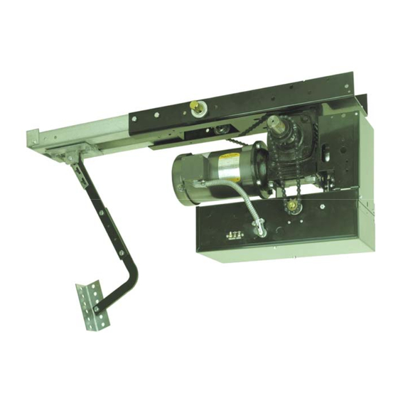
MGT: THE TROLLEY OPERATOR IMPORTANT: UPON COMPLETION OF OPERATOR INSTALLATION, THIS MANUAL MUST BE GIVEN TO THE END-USER 1. PRODUCT APPLICATION The model MGT heavy-duty trolley operator is designed for use on standard lift overhead sectional garage doors. All MGT door operators are designed and constructed in accordance with UL and CSA standards. 2. -
Page 6: Installation
4. INSTALLATION All heavy-duty trolley operators are tested and adjusted at the factory. When installing your unit, please note that the cams are resting in the center of the camshaft. 4.1 IMPORTANT INSTALLATION INSTRUCTIONS WARNING TO REDUCE THE RISK OF SEVERE INJURY OR DEATH, READ AND FOLLOW ALL INSTALLATION INSTRUCTIONS 1. - Page 7 INSTALLATION OF MGT OPERATOR IMPORTANT NOTE: THIS OPERATOR MUST BE INSTALLED A MINIMUM OF 8 FT (2.4 m) ABOVE FLOOR Before the operator is installed, ensure that door has been properly aligned and is working smoothly. It is advisable to assemble the operator to the trolley tracks on the floor prior to installation. Bolt the tracks to the operator using bolts provided (Figure 3).
- Page 8 Figure 6 Installing chain Note: All trolley operators are designed to mount directly over the center of the door, and the operator tracks should clear the door by approximately 2.5" (6.4 cm). If it is not possible to mount the operator exactly centered, it is possible to install it slightly off center for torsion spring doors.
- Page 9 8. After securing the wall mounting bracket, allow the motor to rest on floor and raise the front end of the rails and secure (but not tighten) with 5/16” bolts and nuts (Figure 9). If torsion hardware is preventing the rails from lining- up with the wall bracket, secure temporarily with cord.
- Page 10 13. Close door. Connect door arm to carriage using 3/8" x 2-1/4" bolt furnished. Fasten door bracket to arm and position on door as shown in Figure 12. Mount door bracket to center of door in such a way that the door bracket is also in line with the top rollers on the door.
-
Page 11: Clucth Adjustment
CLUTCH ADJUSTMENT 1. Loosen clutch set screws (Figure 14 A). 2. Back off clutch nut until there is insufficient tension on clutch spring to permit clutch to drive door (Figure 24 B). 3. Tighten clutch nut gradually until there is just enough tension on spring to permit operator to move door smoothly, but allow clutch to slip if door is obstructed. - Page 12 ADJUSTMENT OF LIMIT SWITCHES 1. Open the cover of the electrical enclosure. WARNING NEVER PLACE HANDS OR TOOLS INSIDE OPERATOR OR NEAR DRIVE MECHANISM UNLESS POWER IS OFF Press down on cam retaining plate to rotate cams Rotate cams to desired position Close Cam Open Cam...
-
Page 13: Scheduled Maintenance
All power wiring to the operator should be installed by a qualified electrician and may vary with respect to conduit size and type as specified in the National Electrical Code, Article 430, allowing 5% voltage drop. Power must also be connected in accordance with local codes. TABLE 2 WIRE SIZE vs. -
Page 15: Specific To Electronic Control Board
& &... -
Page 16: Power, Control And Accessory Wiring
7.1 POWER AND CONTROL WIRING DIAGRAM VERY IMPORTANT NOTES • If a push button is not used, a jumper Before installing power and control wiring, be sure to follow must be placed between #8 & #9 all specifications described below. Failure to do so may damage ***Under this condition a stop command is the operator. - Page 17 LOW VOLTAGE (controls) AND HIGH VOLTAGE (power) WIRINGS. Route all low voltage control wires as shown. Keep low voltage wires separate from line voltage wires. Route the power line wires either from right of the control box. WARNING • Wall control(s) must be located so that the door is within sight of the user.
- Page 18 6 7 8 24VAC (10VA MAX.) ONLY FOR THE Power Supply Circuit SUPPLY OF PHOTOCELLS, LOOP 5V DC DETECTORS, KEYPADS… 115/208/230 VAC 1 Ph. 60 Hz 208/230/ 460/575 VAC 3 Ph. 60 Hz Open/Close Open Only White Green AIRSWITCH009 STATION020 2-wire Electric Sensing Edges PULLCORD003 NOTE...
- Page 19 Refer to the wiring diagram on page 16 before connecting power or any external device to the ECB. Neglecting to use the proper terminals will result in complete damage to the ECB. If you are not certain about procedures, please consult Manaras for assistance. NOTE: Do not attempt correction by reversing wires on control station.
-
Page 20: Program Setting
• Program and Program settings Programming ability and door control at electrical box are provided by Open/Close/Stop buttons and Rotary Switch located on the ECB. • Programs PROGRAMS FUNCTIONS AND DESCRIPTIONS The Run Timer stops automatically the operator after an adjustable time delay either travelling RUN TIMER upwards or downwards. -
Page 21: Mode Setting
AVAILABLE TO STOP THE DOOR DURING THE TRAVELLING. WARNING MOTORIZED DOORS CAN CAUSE SEVERE INJURY OR DEATH. MANARAS STRONGLY RECOMMENDS THE USE OF ENTRAPMENT PROTECTION SYSTEMS, ESPECIALLY IN THE CASES OF MOMENTARY CONTACT TO CLOSE (B2 WIRING) AND TIMER TO CLOSE (T & TS). -
Page 22: Door Lock Sensor
7.5 CONNECTION OF A REVERSING EDGE DEVICE IMPORTANT NOTE IF THE DOOR IS CONTROLLED BY ANY DEVICE OTHER THAN A CONSTANT PRESSURE PUSH-BUTTON STATION, A REVERSING EDGE MUST BE CONNECTED. CAUTION: CONNECT REVERSING DEVICE APPROPRIATE TO INSTALLATION. Connection and installation of a reversing edge device is provided with the edge (Figure 17). Any such device that uses a normally open contact may be connected to terminals 3 and 5 on the low voltage terminal block. -
Page 23: Troubleshooting On Ecb
LIMIT SWITCHES WARNING TO AVOID THE DANGER OF POSSIBLE DAMAGE TO THE DOOR AND OPERATOR, TRAVELLING CAMS MUST BE ADJUSTED TO THEIR APPROXIMATE POSITIONS BEFORE MANUALLY OPERATING THE DOOR OR BEFORE APPLYING POWER TO THE OPERATOR. Only 2 limit switches are used in operators built with an Electronic Control Board. One for the “Open” side and one for the “Close”... - Page 24 TROUBLE SHOOTING GUIDE SYMPTOM PROBABLE CAUSE SUGGESTED ACTION Check if STOP Led: if OFF. Disengage the hoist. (JP4 on 2-3 for Check if hoist is not engaged. trolley & sliding operators) Defective “stop” push button. Replace. Door will not respond to « open » Check wiring from push button to operator Replace if needed.
-
Page 27: Single Button Radio Control & Red & Green Warning Lights
& & 8.1 Single button Radio Programming Instructions With the single button radio feature, it is now possible to use a single channel transmitter as a Commercial application and as well as Single Button Radio Control (SBC). The SBC give the possibility to open, stop or close the door by using a single button radio transmitter (or a single push button station). -
Page 28: Warning Lights Sequence
8.2 Warning Light Sequence Lights Operating sequence The light is solid red when the door is closing and opening. Light turns OFF once the door reaches the fully open or fully closed position The green light is ON only when the door is fully open and stays ON during a preset time (programmed Green by the Timer to Close) The red light starts flashing once the green light is OFF and when the door is about to close. - Page 30 WIRING OF THE MGT OPERATOR Do NOT connect any accessory controls until the limit switch adjustments have been completed and the operator is functioning properly. Refer to the electrical diagrams on pages 38 and 39 and to the accessory wiring diagrams on page 32 and 33. WARNING EXERCISE CAUTION WHEN OPERATING MACHINE.
- Page 31 2. A 3 button push-button station (open/close/stop) can be wired to terminals 2, 3, 4 and 5. Two push-button stations can be wired to these same terminals by following the wiring diagrams on pages 38 and 39. Stop Open Close Figure 21 Three button push-button station Three terminals are provided for the wiring of a radio-control receiver.
-
Page 32: Accessory Wirind Diagrams
9.2 Accessory Wiring POWER SUPPLY 115/208/230 1 Ph. 60 Hz Open only White Green 208/230/ 460/575 VAC 3 Ph. 60 Hz Open/Close PULLCORD003 STATION020 AIRSWITCH009 2-wire Electrical Sensing Edges Jumper must be removed if a station with a stop button is Open also connected Close... - Page 33 PHOTO051 FOR MOMENTARY CONTACT TO CLOSE (B2 WIRING), PLEASE REFER TO INSTRUCTION BELOW WARNING Motorized doors can cause serious injuries or death. Manaras strongly recommends the use of entrapment protection systems, especially in the case of momentary contact to close such as with B2 wiring or timer to close.
- Page 34 CONNECTION OF A REVERSING EDGE DEVICE IMPORTANT NOTE: IF THE DOOR IS CONTROLLED BY ANY DEVICE OTHER THAN A CONSTANT PRESSURE PUSH-BUTTON STATION, A REVERSING EDGE MUST BE CONNECTED. CAUTION: CONNECT REVERSING DEVICE APPROPRIATE TO INSTALLATION. Connection and installation of a reversing edge device is provided with the edge (see also Figure 25). Any such device that uses a normally open contact may be connected to terminals 3 and 6 on the low voltage terminal block (Figure 24).
- Page 35 9.4 MANUAL OPERATION OF MGT OPERATOR The MGT operator is equipped with trolley release disconnect mechanism to operate the door manually, if necessary. To manually operate the door: 1. Pull the disconnect chain downwards and disconnect trolley arm from carriage (Figure 27) WARNING DOOR ARM IS RELEASED FROM TROLLEY CARRIAGE WHEN DISCONNECT CHAIN IS PULLED.
-
Page 36: Troubleshooting On Hardwiring Circuit
The following trouble-shooting guide (TABLE 3) will help you identify the source of the problem given a particular symptom. TABLE 3 TROUBLE-SHOOTING GUIDE SYMPTOM PROBABLE CAUSE SUGGESTED ACTION Reset the overload protection: press reset button Motor has overworked and the located on the side of the unit for a single phase overload thermal protection has operator. - Page 37 SYMPTOM PROBABLE CAUSE SUGGESTED ACTION The advanced close limit switch is Replace. Reversing devices will defective. open the door when the The advanced close limit switch needs to The advanced close limit switch is not door is closed. be adjusted just slightly ahead of the end being engaged by travelling cam.
-
Page 40: Warranty Policy
Manaras’ only obligation shall be to repair or replace defective equipment which does not conform to the warranty. Manaras shall not be liable for any injury, loss or damage, direct or consequential, arising out of the inability to use the equipment. Before using, Buyer and/or the ultimate User shall determine the suitability of the product for its intended use, and User assumes all risks and liability in connection therewith. -
Page 41: Notes
NOTES... - Page 42 NOTES...
- Page 43 NOTES...
- Page 44 OPERA Reg. T.M. of 9141-0720 Québec Inc. BOOK169 REV 7 - 2010/08/29...
Need help?
Do you have a question about the Opera MGT and is the answer not in the manual?
Questions and answers