Table of Contents
Advertisement
© 2017 Lennox Industries Inc.
Dallas, Texas USA
C C
I I
HI
AIR FLOW
HORIZONTAL LEFT
Contents
Unit Dimensions .............................................................2
EL280UH Gas Furnace ..................................................3
Shipping and Packing List ..............................................3
Safety Information ..........................................................3
Use of Furnace as Construction Heater .........................4
General ...........................................................................4
Combustion, Dilution & Ventilation Air ............................5
Setting Equipment .........................................................8
Filters ............................................................................ 11
Duct System .................................................................12
Venting..........................................................................13
UPFLOW
AIR FLOW
AIR FLOW
HORIZONTAL RIGHT
INSTALLATION
INSTRUCTIONS
EL280UH
ELITE ® SERIES GAS FURNACE
UPFL0W / HORIZONTAL AIR DISCHARGE
507333-01
11/2017
Supersedes 05/2016
THIS MANUAL MUST BE LEFT WITH THE
HOMEOWNER FOR FUTURE REFERENCE
This is a safety alert symbol and should never be
ignored. When you see this symbol on labels or in man-
uals, be alert to the potential for personal injury or death
As with any mechanical equipment, contact with sharp
sheet metal edges can result in personal injury. Take
care while handling this equipment and wear gloves and
protective clothing.
Improper installation, adjustment, alteration, service
or maintenance can cause property damage, personal
injury or loss of life. Installation and service must be
performed by a licensed professional HVAC installer or
equivalent, service agency, or the gas supplier.
Gas Piping ....................................................................21
Electrical .......................................................................23
Integrated Control .........................................................28
Unit Start Up .................................................................29
Gas Pressure Adjustment .............................................30
Proper Combustion.......................................................31
High Altitude .................................................................31
Other Unit Adjustments.................................................32
Sequence of Operation.................................................32
Service..........................................................................34
Repair Parts List ...........................................................36
Start-Up & Performance Checl List ..............................37
Page 1
CAUTION
WARNING
Advertisement
Table of Contents

Related Manuals for Lennox EL280UH070P24A


Summary of Contents for Lennox EL280UH070P24A
-
Page 1: Table Of Contents
INSTALLATION INSTRUCTIONS EL280UH © 2017 Lennox Industries Inc. Dallas, Texas USA ELITE ® SERIES GAS FURNACE UPFL0W / HORIZONTAL AIR DISCHARGE 507333-01 11/2017 Supersedes 05/2016 THIS MANUAL MUST BE LEFT WITH THE HOMEOWNER FOR FUTURE REFERENCE This is a safety alert symbol and should never be ignored. -
Page 2: Unit Dimensions
Unit Dimensions - inches (mm) 3-1/8 (79) NOTE - 60C and 60D size units that require second stage air volumes over 1800 cfm (850 L/s) must have one of the following: 1. Single side return air with transition, to accommodate 20 x 25 x 1 in. -
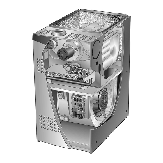
Page 3: El280Uh Gas Furnace
CAUTION EL280UH Gas Furnace The EL280UH unit is shipped ready for installation in the As with any mechanical equipment, contact with sharp upflow or horizontal right position (for horizontal left posi- sheet metal edges can result in personal injury. Take tion the combustion air pressure switch must be moved). -
Page 4: Use Of Furnace As Construction Heater
Use of Furnace as Construction Heater When this furnace is used with cooling units, it shall be in- Lennox does not recommend the use of EL280UH units stalled in parallel with, or on the upstream side of, cooling as a construction heater during any phase of construc- units to avoid condensation in the heating compartment. -
Page 5: Combustion, Dilution & Ventilation Air
• Do not install the furnace where drafts might blow CAUTION directly into it. This could cause improper combus- Insufficient combustion air can cause headaches, tion and unsafe operation. nausea, dizziness or asphyxiation. It will also cause • Do not block the furnace combustion air openings excess water in the heat exchanger resulting in rusting with clothing, boxes, doors, etc. - Page 6 Confined Space Air from Inside A confined space is an area with a volume less than 50 If the confined space that houses the furnace adjoins a cubic feet (1.42 m3) per 1,000 Btu (.29 kW) per hour of space categorized as unconfined, air can be brought in by the combined input rating of all appliances installed in that providing two permanent openings between the two spac- space.
- Page 7 EQUIPMENT IN CONFINED SPACE ALL AIR FROM OUTSIDE (Inlet Air from Crawlspace and Outlet Air to Ventilated Attic) CHIMNEY OR GAS VENT VENTILATION LOUVERS (Each end of attic) OUTLET WATER FURNACE HEATER INLET VENTILATION LOUVERS (For unheated crawl space) AIR FLOW NOTE-The inlet and outlet air openings shall each have a free area of at least one square inch (645 ) per 4,000 Btu (1.17 kW) per hour of the total input rating of all equipment in the enclosure.
-
Page 8: Setting Equipment
Upflow Applications Setting Equipment Allow for clearances to combustible materials as indicated WARNING on the unit nameplate. Minimum clearances for closet or alcove installations are shown in figure 7. Do not install the furnace on its front or its back. Do not connect the return air ducts to the back of the furnace. -
Page 9: Return Air
Return Air -- Upflow Applications Single Side Return Air Return air can be brought in through the bottom or either (with transition and filter) side of the furnace installed in an upflow application. If the furnace is installed on a platform with bottom return, make an airtight seal between the bottom of the furnace and the platform to ensure that the furnace operates properly and safely. - Page 10 Pivot the bottom cap down to release the bottom plications. Order horizontal suspension kit (51W10) from panel. Once the bottom panel has been removed, reinstall Lennox, or use equivalent suspension method. Allow for the bottom cap. See figure 10. clearances to combustible materials as indicated on the unit nameplate.
-
Page 11: Filters
Lennox Product living space. Use screws and joint tape to seal the return Specifications bulletin. Additional information is provided air system to the furnace. -
Page 12: Duct System
Return Air Plenum Duct NOTE - Return air must not be drawn from a roomwhere Use industry-approved standards (such as those pub- this furnace, or any other gas-fueled appliance (i.e., water lished by Air Conditioning Contractors of America or Amer- heater), or carbon monoxide producing device (i.e., wood ican Society of Heating, Refrigerating and Air Condition- fireplace) is installed. -
Page 13: Venting
If necessary reposition the combustion air inducer, pres- Venting sure switch and or make up box as needed per the follow- A 4-inch diameter flue transition is factory-installed on ing steps and see figures 16 through 21. the combustion air inducer outlet of all models. Figure 15 1 - Remove the four mounting screws which secure the shows the combustion air inducer as shipped from the fac- combustion air inducer / pressure switch assembly... - Page 14 HORIZONTAL RIGHT POSITION HORIZONTAL LEFT POSITION Top Vent Discharge Top Vent Discharge Vent Pipe Vent Pipe Pressure Switch Pressure Switch Flue Transition Cover Plate Flue Transition FLOW FLOW Collector Box Cover Plate Collector Box Make-Up Box Make-Up Box Disconnect Gas supply piping must be brought into the unit from the bottom sure switch assembly.
- Page 15 Venting Using a Masonry Chimney The EL280UH series units are classified as fan-assisted Category I furnaces when vertically vented according to The following additional requirements apply when a lined the latest edition of National Fuel Gas Code (NFPA 54 / masonry chimney is used to vent this furnace.Masonry ANSI Z223.1) in the USA.
- Page 16 A type B1 vent or masonry chimney liner shall terminate Common Venting Using Metal-Lined Masonry Chimney above the roof surface with a listed cap or a listed roof as- sembly according to the terms of their respective listings SEALED and the vent manufacturer’s instructions. MAX.
- Page 17 Common Venting Using Tile-Lined Interior Masonry Chimney and Combined Vent Connector MINIMUM LENGTH = AS SHORT AS PRACTICAL. INTERIOR TILE-LINED FOR MAXIMUM LENGTH SEE NOTE TO LEFT MASONRY CHIMNEY NOTE- Refer to provided venting tables for installations. NOTE - the chimney must be properly sized per provided venting tables or lined with listed metal lining system.
- Page 18 16 - Vent connectors serving Category I appliances shall 20 - Do not install a manual damper, barometric draft not be connected to any portion of mechanical draft regulator or flue restrictor between the furnace and systems operating under positive pressure such as the chimney.
- Page 19 TABLE 4 Vent Connector Capacity Type B Double-Wall Vents with Type B Double-Wall Connectors Serving Two or More Category I Appliances Vent and Connector Diameter - D (inches) Height Lateral 3 inch 4 inch 5 inch 6 inch Appliance Input Rating in Thousands of Btu Per Hour (feet) (feet) TABLE 5...
- Page 20 Removal of the Furnace from Common Vent 3 - Close all building doors and windows and all doors between the space in which the appliances In the event that an existing furnace is removed from a remaining connected to the common venting system venting system commonly run with separate gas applianc- are located and other spaces of the building.
-
Page 21: Gas Piping
2 - When connecting the gas supply piping, consider Gas Piping factors such as length of run, number of fittings, and Gas supply piping should not allow more than 0.5”W.C. furnace rating to avoid excessive pressure drop. drop in pressure between gas meter and unit. Supply gas Table 6 lists recommended pipe sizes for typical pipe must not be smaller than unit gas connection applications. - Page 22 Left Side Piping MANUAL (Standard) MAIN SHUT-OFF AUTOMATIC MANUAL VALVE GAS VALVE MAIN SHUT-OFF (With 1/8 in. NPT AUTOMATIC VALVE Plugged Tap GAS VALVE (With 1/8 in. NPT Shown) Plugged Tap Shown) GROUND JOINT UNION GROUND JOINT UNION DRIP LEG Right Side Piping FIELD (Alternate)
-
Page 23: Electrical
Leak Check WARNING After gas piping is completed, carefully check all piping Fire Hazard. Use of aluminum wire with this product may connections (factory- and field-installed) for gas leaks. result in a fire, causing property damage, severe injury Use a leak detecting solution or other preferred means. or death. - Page 24 Generator Use - Voltage Requirements Complete the wiring connections to the equipment. Use the provided unit wiring diagram and the field wiring dia- The following requirements must be kept in mind when gramshown in figure 29. Use 18-gauge wire or larger that specifying a generator for use with this equipment: is suitable for Class II rating for thermostat connections.
- Page 25 TABLE 7 Field Wiring Applicatuions DIP Switch Settings and On-Board Links (See figure 30) W915 Thermostat Two-Stage W951 Wiring Connections DIP Switch 1 Cooling Heat Pumps 1 Heat / 1 Cool Intact Intact CONTROL OUTDOOR T'STAT TERM. STRIP UNIT NOTE - Use DIP ond-stage heat ON delay.
- Page 26 TABLE 7 Field Wiring Applicatuions DIP Switch Settings and On-Board Links (See figure 30) W915 Thermostat Wiring Connections Two-Stage W951 DIP Switch 1 Cooling Heat Pumps 2 Heat / 2 Cool Intact CONTROL OUTDOOR T'STAT TERM. STRIP UNIT 2 Heat / 1 Cool Intact Intact CONTROL...
- Page 27 EL280UH Schematic Wiring Diagram FIGURE 29 Page 27...
-
Page 28: Integrated Control
THERMOSTAT CONNECTIONS (TB1) SWITCHES ON-BOARD LINKS 1= ERROR CODE RECALL H= 24V HUMIDIFIER OUTPUT L= LENNOX SYSTEM OPERATION MONITOR DIP SWITCH FUNCTIONS W915 1 -- 2 Stage T'stat Selects t/stat type (single or two-stage) W951 2 -- 2nd Stage Delay Second stage ON delay (single-stage t'stat) 3 &... -
Page 29: Unit Start Up
WARNING TABLE 8 Heating Blower-Off Delay Switch Settings If overheating occurs or if gas supply fails to shut off, Blower Off Delay shut off the manual gas valve to the appliance before Switch 3 Switch 4 (Seconds) shutting off electrical supply. CAUTION factory setting Before attempting to perform any service or maintenance,... -
Page 30: Gas Pressure Adjustment
Failure To Operate NOTE - Pressure test adapter kit (10L34) is available from Lennox to facilitate manifold pressure measurement. If the unit fails to operate, check the following: 1 - Connect test gauge to manifold pressure post 1 - Is the thermostat calling for heat? (figure 31) gas valve. -
Page 31: Proper Combustion
Proper Combustion High Altitude Furnace should operate minimum 15 minutes with correct The manifold pressure may require adjustment and com- manifold pressure and gas flow rate before checking com- bustion air pressure switch may need replacing to ensure bustion. Table 10 shows acceptable combustion for ALL proper combustion at higher altitudes. -
Page 32: Other Unit Adjustments
Electrical Other Unit Adjustments 1 - Check all wiring for loose connections. Primary and Secondary Limits 2 - Check for the correct voltage at the furnace (furnace The primary limit is located on the heating compartment operating). Correct voltage is 120VAC + 10%. vestibule panel. - Page 33 NOTE - If the low fire pressure switch does not close the Combustion air inducer runs until S128 low heat prove switch contacts close (switch must close within 2 1/2 combustion air inducer will switch to high fire. After a 15 second pre-purge the high fire pressure switch will close minutes or control goes into Watchguard Pressure and the unit will begin operation on high fire.
-
Page 34: Service
At the beginning of each heating season, and to comply off operation. with the Lennox Limited Warranty, your system should 1 - Check the operation of the ignition system, inspect be checked as follows: and clean flame sensor. - Page 35 Cleaning the Burners 4 - To clean burners, run a vacuum cleaner with a soft brush attachment over the face of burners. Visually NOTE - Use papers or protective covering in front of the inspect inside the burners and crossovers for any furnace during cleaning.
-
Page 36: Repair Parts List
Repair Parts List The following repair parts are available through independent Lennox dealers. When ordering parts, include the complete furnace model number listed on the CSA International nameplate -- Example: EL280UH045P24A-01. All service must be performed by a licensed professional HVAC installer (or equivalent), service agency, or gas supplier. -
Page 37: Start-Up & Performance Checl List
Start-Up & Performance Check List UNIT SET UP (typical) Unit Model Number_______________ Serial Number___________________ SUPPLY Line Voltage upflow furnace shown Gas Supply Pressure Filter RETURN RETURN DUCT SYSTEM GAS SUPPLY SUPPLY AIR DUCT LP/Propane Gas Natural Gas Sealed Piping Connections Tight Insulated (if necessary) Leak Tested Registers Open and Unobstructed... - Page 38 UNIT OPERATION (typical) Combustion CO SUPPLY Thermostat Gas Manifold Pressure Temperatures upflow furnace shown Filter Blower Motor Amps Duct Static RETURN RETURN COOLING MODE HEATING MODE INDOOR BLOWER AMPS______ GAS MANIFOLD PRESSURE “W.C._____ TEMPERATURE DROP COMBUSTION SAMPLE CO CO PPM_______ ______ Return Duct Temperature _________ Supply Duct Temperature...
Need help?
Do you have a question about the EL280UH070P24A and is the answer not in the manual?
Questions and answers