Advertisement
Table of Contents
- 1 Table of Contents
- 2 Specifications
- 3 High Altitude Derate
- 4 Blower Data
- 5 I Unit Components
- 6 Installation
- 7 Start up
- 8 Heating System Service Checks
- 9 Typical Operating Characteristics
- 10 Maintenance
- 11 Wiring and Sequence of Operation
- 12 Field Wiring and DIP Switch Settings
- 13 Troubleshooting
- 14 Troubleshooting: Cooling Sequence of Operation
- Download this manual
See also:
Instruction and Installation Manual
Service Literature
EL280UH(X) series units are 80% efficiency gas furnaces
used for upflow or horizontal applications only, manufac-
tured with Lennox Duralokt heat exchangers formed of
aluminized steel. EL280UH(X) units are available in heat-
ing capacities of 66,000 to 132,000 Btuh and cooling ap-
plications up to 5 tons. Product Specifications manual for
proper sizing.
Units are factory equipped for use with natural gas. Kits are
available for conversion to LPG operation. EL280UH(X)
model units are equipped with the SureLight
tegrated control. EL280UH(X) unit meets the California Ni-
trogen Oxides (NO
) Standards and California Seasonal Ef-
x
ficiency requirements. All units use a redundant gas valve to
assure safety shut−off as required by C.S.A.
All specifications in this manual are subject to change. Pro-
cedures outlined in this manual are presented as a recom-
mendation only and do not supersede or replace local or
state codes. In the absence of local or state codes, the
guidelines and procedures outlined in this manual (except
where noted) are recommendations only and do not consti-
tute code.
TABLE OF CONTENTS
. . . . . . . . . . . . . . . . . . . . . . . . . . . . .
. . . . . . . . . . . . . . . . . . . . . . . . . . . . . .
. . . . . . . . . . . . . . . . . . . . . . . .
. . . . . . . . . . . . . . . . . . . . . . . . . . . . .
. . . . . . . . . . . . . . . . . . . . . . . . . . . . . . .
. . . . . . . . . . . . . . . . . . . . . . . . . .
. . . . . . . . . . . . . . . . . . . . . . .
Corp. 1138−L11
Revised 05/2012
EL280UH(X) SERIES UNITS
®
two−stage in-
Page 2
Page 5
Page 8
Page 19
Page 19
. . . . . . . . .
Page 19
. . . . . . . . .
Page 22
Page 23
. . . . . .
Page 26
. . . .
Page 28
Page 30
Page 1
EL280UH(X)
WARNING
Improper installation, adjustment, alteration, service
or maintenance can cause property damage, person-
al injury or loss of life. Installation and service must
be performed by a licensed professional installer (or
equivalent), service agency or the gas supplier.
WARNING
Sharp edges.
Be careful when servicing unit to avoid sharp edges
which may result in personal injury.
© 2012 Lennox Industries Inc.
Advertisement
Table of Contents

Related Manuals for Lennox EL280UH110P60C


Summary of Contents for Lennox EL280UH110P60C
-
Page 1: Table Of Contents
EL280UH(X) series units are 80% efficiency gas furnaces used for upflow or horizontal applications only, manufac- tured with Lennox Duralokt heat exchangers formed of aluminized steel. EL280UH(X) units are available in heat- ing capacities of 66,000 to 132,000 Btuh and cooling ap- plications up to 5 tons. -
Page 2: Specifications
SPECIFICATIONS Model No. EL280UH070P24A EL280UH070P36A EL280UH090P36B Heating Model No. - Low Nox - - - EL280UH070XP36A - - - Performance AFUE High Input - Btuh 66,000 66,000 88,000 Fire Output - Btuh 52,000 53,000 70,000 Temperature rise range - °F 40 - 70 30 - 60 35 - 65... - Page 3 SPECIFICATIONS Model No. EL280UH110P60C EL280UH135P60D Heating Model No. - Low Nox EL280UH110XP60C - - - Performance AFUE High Input - Btuh 110,000 132,000 Fire Output - Btuh 87,000 106,000 Temperature rise range - °F 30 - 60 35 - 65 Gas Manifold Pressure (in.
-
Page 4: High Altitude Derate
OPTIONAL ACCESSORIES - ORDER SEPARATELY NOTE - FURNACES CANNOT BE TWINNED! “A” Width “B” Width “C” Width “D” Width Models Models Models Models CABINET ACCESSORIES Horizontal Suspension Kit - Horizontal only 51W10 51W10 51W10 51W10 Return Air Base - Upflow only 65W75 50W98 50W99... -
Page 5: Blower Data
BLOWER DATA EL280UH070P24A PERFORMANCE (Less Filter) EL280UH090P36B PERFORMANCE (Less Filter) Air Volume / Watts at Various Blower Speeds Air Volume / Watts at Various Blower Speeds External External Medium- Medium- Medium- Medium- Static Static High High High High Pressure Pressure in. - Page 6 BLOWER DATA EL280UH110P60C PERFORMANCE (Less Filter) Air Volume / Watts at Different Blower Speeds Bottom Return Air, Side Return Air with Optional Return Single Side Return Air − Air volumes in bold require field External Air Base, Return Air from Both Sides or Return Air from fabricated transition to accommodate 20 x 25 x 1 in.
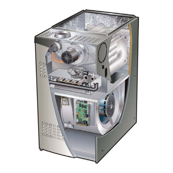
- Page 7 EL280UH Parts Arrangement Make Up Box Heat Exchanger Combustion Air Inducer Combustion Air Pressure Switch Gas Valve and Manifold Assembly Collector Box Indoor Blower and Motor Assembly (installed in cabinet) Limit Switch (under collector box) Transformer Door Interlock Integrated Control Switch Indoor Blower and Motor Assembly (removed from cabinet)
-
Page 8: I Unit Components
A− Control Box 1. Control Transformer (T1) 4. Integrated Control (A92) EL280UH units are equipped with the Lennox two−stage A transformer located in the control box provides power to ® integrated SureLight control. The system consists of a the low voltage section of the unit. - Page 9 After the 15−second pre−purge period, the SureLight ignitor Switch 2 −− Second Stage Delay (Used with Single− warms up for 20 seconds after which the gas valve opens Stage Thermostat Only) −− This switch is used to deter- for a 4−second trial for ignition. The ignitor energizes during mine the second stage on delay when a single−stage ther- the trial until flame is sensed.
- Page 10 DIAGNOSTIC LEDs THERMOSTAT CONNECTIONS (TB1) SWITCHES ON−BOARD LINKS 1= ERROR CODE RECALL H= 24V HUMIDIFIER OUTPUT L= LENNOX SYSTEM OPERATION MONITOR DIP SWITCH FUNCTIONS W915 DIP SWITCH(ES) FUNCTION 1 −− 2 Stage T’stat Selects t/stat type (single or two−stage) W951 2 −−...
- Page 11 INTEGRATED CONTROL FIGURE 6 Page 11...
- Page 12 TABLE 4 FLASH CODE STATUS / ERROR DESCRIPTION (X + Y) FLASH CODE DESCRIPTIONS Pulse A 1/4 second flash followed by four seconds of off time. Heartbeat Constant 1/2 second bright and 1/2 second dim cycles. LED flashes X times at 2Hz, remains off for two seconds, flashes Y times at 2Hz, remains off for four X + Y seconds, then repeats.
- Page 13 Inlet and outlet pressure taps are located on the valve. A regu- lator adjustment screw is located on the valve. 5. Blower Motors and Capacitors LPG change over kits are available from Lennox. Kits include All EL280UH(X) units use direct drive blower motors. All mo- burner orifices.
- Page 14 EL280UH HEATING COMPONENTS Ignitor Burners Rollout Switches Sensor Gas Valve Gas Orifices FIGURE 7 Page 14...
- Page 15 To Measure Flame Signal − Integrated Control: 6 − Turn supply voltage on and close thermostat contacts to cycle system. Use a digital readout meter capable of reading DC micro- 7 − When main burners are in operation for two minutes, take amps.
- Page 16 EL280UH Ignitor Check Out Test 1 Checking resistance of ignitor circuit Remove 5−pin plug from integrated control. Check Ohms reading across terminal 1 and 5. Reading should be between 39 and 70 ohms. If value is correct, this is the only test needed. If the meter reading is not correct ("0"...
- Page 17 NOTE − Each furnace model uses a unique CAI. Refer to the vestibule to purge switch tubing, to prevent condensate build up. Lennox Repair Parts listing for correct inducer for replace- ment. A pressure switch connected to the combustion air inducer COMBUSTION AIR PRESSURE SWITCH orifice plate is used to prove inducer operation.
- Page 18 Multiple Venting screws, rotate the combustion air inducer and gasket (pressure switch should be above the combustion air in- The EL280UH(X) furnace can vent in multiple positions. ducer in all positions), then reinstall the mounting screws. See figure 11. See unit Installation Instructions for more detail. The make up box may be removed and the combustion air IMPORTANT inducer may be rotated clockwise or counterclockwise 90°...
-
Page 19: Installation
II−PLACEMENT AND INSTALLATION NOTE − When unit is initially started, steps 1 through 11 may need to be repeated to purge air from gas line. Make sure unit is installed in accordance with installation Turning Off Gas To Unit instructions and applicable codes. 1 −... - Page 20 Gas Leak Detector is strongly recommended. It is available more accurate time.) Divide by two and compare to time through Lennox under part number 31B2001. See Corp. in table 8 below. If manifold pressure matches table 10 8411−L10, for further details.
- Page 21 TABLE 9 IMPORTANT Firing Rate For Nat For L.P. High Fire 6.0 − 7.5 7.0 − 8.5 For safety, shut unit off and remove manometer as soon as an accurate reading has been obtained. Low Fire 5.0 − 6.5 5.8 − 7.3 Take care to replace pressure tap plug.
-
Page 22: Typical Operating Characteristics
V−TYPICAL OPERATING CHARACTERISTICS C−External Static Pressure A−Blower Operation and Adjustment 1 − Tap locations shown in figure 15. 1 − Blower operation is dependent on thermostat control 2 − Punch a 1/4" diameter hole in supply and return air ple- system. -
Page 23: Maintenance
VI−MAINTENANCE E−Heat Exchanger and Burners Cleaning the Heat Exchanger and Burners WARNING NOTE − Use papers or protective covering in front of the fur- nace during cleaning. Disconnect power before servicing unit. 1 − Turn off both electrical and gas power supplies to fur- nace. - Page 24 EL280UH BURNER, COMBUSTION AIR INDUCER ASSEMBLY & HEAT EXCHANGER REMOVAL Gasket Pressure Switch Flue Transition Collector Box Heat Exchanger Ignitor Orifice Plate Combustion Air Inducer Retention Rings Rollout Switches Sensor Cross Over Manifold And Gas Valve FIGURE 1 EL280UH NOx INSERTS NOx Insert FIGURE 2 Page 24...
- Page 25 18 −Reconnect all wires. Remove 5 screws if necessary (either side of cabinet) 19 −Reconnect top cap and vent pipe to combustion air in- ducer outlet. 20 −Reconnect gas supply piping. 21 −Turn on power and gas supply to unit. 22 −Set thermostat and check for proper operation.
-
Page 26: Wiring And Sequence Of Operation
FACTORY DEFAULT IS FOR A 2 STAGE THERMOSTAT TERMINAL #1 IS USED FOR ERROR CODE RECALL ONLY. SEE INSTALLATION INSTRUCTIONS FOR DETAILS. 24V POWER IS PROVIDED FOR OPTIONAL HUMIDIFIER DURING HEAT DEMAND BURNER ASSY GND 120V EL280UH070P24A EL280UH110P60C EL280UH070P36A EL280UH135P60D EL280UH090P36B EL280UH070XP36A EL280UH090P48B EL280UH090XP48B EL280UH110XP60C EL280UH110P48C... - Page 27 Integrated Control Self Check Single−Stage Thermostat, Two Stage Heat. Dip Switch set at ON" When there is a call for heat, the integrated control runs a self check. The control checks for S10 primary limit, S21 1− SureLight control energizes combustion air inducer B6 on low heat speed.
-
Page 28: Field Wiring And Dip Switch Settings
VIII− Field Wiring and DIP Switch Settings TABLE 12 Field Wiring Applications DIP Switch Settings and On−Board Links (See figure 6) W915 Thermostat W951 Wiring Connections Two−Stage DIP Switch 1 Cooling Heat Pumps 1 Heat / 1 Cool Intact Intact CONTROL OUTDOOR T’STAT... - Page 29 TABLE 12 Field Wiring Applications (Continued) DIP Switch Settings and On−Board Links (See figure 6) W915 Thermostat Wiring Connections Two−Stage W951 DIP Switch 1 Cooling Heat Pumps 2 Heat / 2 Cool Intact CONTROL OUTDOOR T’STAT TERM. STRIP UNIT 2 Heat / 1 Cool Intact Intact CONTROL...
-
Page 30: Troubleshooting
IX− Troubleshooting Troubleshooting: Heating Sequence of Operation HEATING SEQUENCE OF OPERATION NORMAL AND ABNORMAL HEATING MODE POWER ON GAS VALVE OFF. COMBUSTION AIR INDUCER OFF. INDOOR BLOWER OFF. (RESET CONTROL BY CONTROL SELF−CHECK OKAY? TURNING MAIN POWER OFF.) POLARITY REVERSED. POLARITY OKAY? STATUS ERROR CODE 5 + 4. - Page 31 Troubleshooting: Heating Sequence of Operation (Continued) HEATING SEQUENCE OF OPERATION CONTINUED THERMOSTAT CALLS FOR HEAT STATUS LED − HEARTBEAT. (Refer to box A on previous page) GAS VALVE OFF. COMBUSTION AIR INDUCER FIRST−STAGE (LOW FIRE) PRESSURE OFF. INDOOR BLOWER OFF. UNIT WILL RETRY SWITCH CLOSED WITHIN 2.5 MINUTES? AFTER 5−MINUTE WAIT PERIOD.
- Page 32 Troubleshooting: Heating Sequence of Operation (Continued) HEATING SEQUENCE OF OPERATION CONTINUED THERMOSTAT CALLS FOR HEAT. STATUS LED −− HEARTBEAT. SEE BOX A. FLAME SIGNAL ABOVE (u1.40 microamps) LOW FLAME SIGNAL (Does not affect control operation) STATUS ERROR CODE 1 + 2. SINGLE−STAGE THERMOSTAT MODE TWO STAGE THERMOSTAT MODE (DIP SWITCH SET AT ON")
- Page 33 Troubleshooting: Heating Sequence of Operation (Continued) HEATING SEQUENCE OF OPERATION CONTINUED SEE BOX A NORMAL OPERATION. SEE BOX B THERMOSTAT CALLS FOR HEAT. RETURN TO FIRST−STAGE HEAT MODE. FIRST−STAGE CONTINUES UNTIL SECOND− STAGE PRESSURE SWITCH CAN BE PROVEN SECOND−STAGE (HIGH FIRE) HEAT or HEAT DEMAND IS SATISFIED.
-
Page 34: Troubleshooting: Cooling Sequence Of Operation
Troubleshooting: Cooling Sequence of Operation COOLING SEQUENCE OF OPERATION POWER ON SIGNAL POLARITY REVERSED. CONTROL WILL CONTINUE TO CALL FOR COOLING IS POLARITY REVERSED? IN THIS CONDITION. STATUS ERROR CODE 5 + 4. SIGNAL IMPROPER GROUND AT LED. CONTROL WILL CONTINUE TO CALL FOR COOLING IS THERE IN THIS CONDITION. - Page 35 Troubleshooting: Continuous Fan Sequence of Operation CONTINUOUS LOW SPEED FAN SEQUENCE OF OPERATION MANUAL FAN SELECTION MADE AT THERMOSTAT. AFTER 2 SECOND DELAY, INDOOR BLOWER IS ENERGIZED ON CONTINUOUS FAN SPEED. THERMOSTAT CALLS FOR FIRST STAGE COOL. THERMOSTAT CALLS FOR FIRST−STAGE HEAT. INDOOR BLOWER RAMPS TO FIRST STAGE AFTER 45−SECOND DELAY, INDOOR BLOWER COOLING SPEED AFTER A 2−SECOND DELAY.
Need help?
Do you have a question about the EL280UH110P60C and is the answer not in the manual?
Questions and answers