Table of Contents
Advertisement
S e r v i c e L i t e r a t u r e
EL280DFE series units are 80% efficiency gas furnaces
used for downflow applications only, manufactured with
Lennox Duralok heat exchangers formed of aluminized
steel. Units are available in heating capacities of 66,000 to
88,000 Btuh and cooling applications up to 4 tons. Refer
to Engineering Handbook for proper sizing.
Units are factory equipped for use with natural gas. Kits
are available for conversion to LPG operation. EL280DFE
model units are equipped with the SureLight® integrated
control. All units use a redundant gas valve to assure safe-
ty shut-off as required by CSA.
All specifications in this manual are subject to change.
Procedures outlined in this manual are presented as a
recommendation only and do not supersede or replace lo-
cal or state codes. In the absence of local or state codes,
the guidelines and procedures outlined in this manual (ex-
cept where noted) are recommendations only and do not
constitute code.
WARNING
Improper
installation,
service or maintenance can cause property damage,
personal injury or loss of life. Installation and service
must
be performed by a licensed professional
HVAC installer or equivalent, service agency, or the
gas supplier.
TABLE OF CONTENTS
Specifications . . . . . . . . . . . . . . . . . . . . . . . . . . . . . Page 2
Blower Performance Data . . . . . . . . . . . . . . . . . . Page 3
Parts Identification . . . . . . . . . . . . . . . . . . . . . . . . . Page 4
I Unit Components . . . . . . . . . . . . . . . . . . . . . . . . Page 5
IInstallation . . . . . . . . . . . . . . . . . . . . . . . . . . . . Page 21
III Start Up . . . . . . . . . . . . . . . . . . . . . . . . . . . . . . Page 21
IV Heating System Service Checks . . . . . . . . . Page 23
V Typical Operating Characteristics . . . . . . . . . Page 25
VI Maintenance . . . . . . . . . . . . . . . . . . . . . . . . . . Page 26
VII Wiring and Sequence of Operation . . . . . . Page 29
VIII Field Wiring and DIP Switch Settings . . . . Page 33
IX Troubleshooting Flow Chart . . . . . . . . . . . . . Page 37
UNIT INFORMATION
UNIT INFORMATION
Corp 1902-L1
EL280DFE SERIES UNITS
adjustment,
alteration,
05/2022
Electric shock hazard. Can cause injury
or death. Before attempting to perform
any service or maintenance, turn the
electrical power to unit OFF at disconnect
switch(es). Unit may have multiple power
supplies.
As with any mechanical equipment, contact with
sharp sheet metal edges can result in personal
injury. Take care while handling this equipment and
wear gloves and protective clothing.
Page 1
EL280DFE
C C C C
HI
HI
I I I I
WARNING
CAUTION
©2016 Lennox Industries, Inc.
Advertisement
Table of Contents

Related Manuals for Lennox EL280DF070E36A


Summary of Contents for Lennox EL280DF070E36A
-
Page 1: Table Of Contents
EL280DFE series units are 80% efficiency gas furnaces used for downflow applications only, manufactured with Lennox Duralok heat exchangers formed of aluminized steel. Units are available in heating capacities of 66,000 to 88,000 Btuh and cooling applications up to 4 tons. Refer to Engineering Handbook for proper sizing. -
Page 2: Specifications
SP ECIF ICATIONS Model No. EL280DF070E36A EL280DF090E48B Heating AFUE Performance High Input - Btuh 66,000 88,000 Fire Output - Btuh 52,000 69,000 Temperature rise range - °F 30 - 60 35 - 65 Gas Manifold Pressure (in. w.g.) 3.5 / 10.0 3.5 / 10.0... -
Page 3: Blower Performance Data
BLO WER DATA EL280DF070E36A PERFORMANCE (Less Filter) Air Volume / Watts at Various Blower Speeds External High Medium-High Medium Medium-Low Static (Black) (Brown) (Blue) (Yellow) (Red) Pressure in. w.g. Watts Watts Watts Watts Watts 0.00 1475 1345 1190 0.10 1440... -
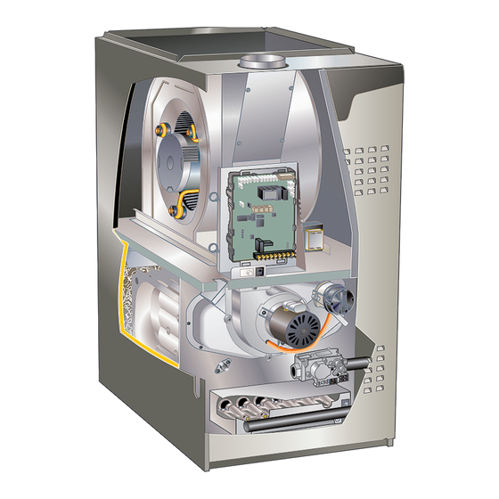
Page 4: Parts Identification
PARTS IDENTIFICATION Top Cap Secondary Limit Indoor Blower Control Box (includes integrated control, transformer and door switch) Internal Flue Pipe Assembly Heat Exchanger Combustion Air Inducer Burner Box Assembly Primary Limit Gas Valve Access Panel FIGURE 1 Page 4... -
Page 5: I Unit Components
I-UNIT COMPONENTS CIRCUIT BREAKER CB8 Unit components are shown in FIGURE 1. The gas valve, combustion air inducer and burners can be accessed by removing the access panel. Electrical components are in PRESS TO RESET the control box (FIGURE 2) found in the blower section. ELECTROSTATIC DISCHARGE (ESD) Precautions and Procedures FIGURE 3... - Page 6 After the 15-second pre-purge period, the SureLight ® TABLE 1 nitor warms up for 20 seconds after which the gas valve SureLight Control 5 Pin Terminal Designation ® opens for a 4-second trial for ignition. The ignitor remains Pin # Function energized during the trial until flame is sensed.
- Page 7 Integrated Control 103699 INTEGRATED CONTROL 24VAC Indoor Ignitor and Combustion Blower Terminals Air Inducer Neutrals Flame Sense S4 DIP Switches Diagnostic Push Button On Board Links THERMOSTAT CONNECTIONS (TB1) 3/16” QUICK CONNECT TERMINALS DS = DEHUMIDIFICATION SIGNAL FLAME SENSE SIGNAL W2 = HEAT DEMAND FROM 2ND STAGE T/STAT HI COOL 24VAC W1 = HEAT DEMAND FROM 1ST STAGE T/STAT...
- Page 8 Integrated Control 107048 Line Voltage Ignitor and Combustion Accessories Air Inducer Humidifier Neutrals Flame Sense On Board Links FIGURE 5 Page 8...
- Page 9 INTEGRATED CONTROL CONFIGURATION GUIDE 2ND STAGE HEAT ON DELAY 7 MIN UPSTAGE THERMOSTAT SELECTION DELAY COOLING BLOWER-OFF DELAY TWO STAGE THERMOSTAT 12 MIN UPSTAGE *45 SECOND COOL BLOWER DELAY 1−STAGE OFF DELAY THERMOSTAT (TIMED STAGING) −SEE SW #2 HSI/CAI 2 SECOND COOL BLOWER HEATING BLOWER−OFF DELAY OFF DELAY...
- Page 10 TABLE 3 Integrated Control Diagnostic Modes Display Action (when button released) No Change Remain in idle mode Solid “E” Enter diagnostic recall mode Solid “F” Enter flame signal mode TABLE 4 Integrated Diagnostic Codes/Status of Equipment Code Diagnostic Codes/Status of Equipment Action Required to Clear and Recover Idle mode (Decimal blinks at 1 Hertz -- 0.5 second ON, 0.5 second OFF).
- Page 11 TABLE 4 Continued Code Diagnostic Codes/Status of Equipment Action Required to Clear and Recover E125 Control failed self-check, internal error, Hardware problem on the control. Cycle power on control. Replace failed hardware. Will restart if error recovers. if problem prevents service and is persistent. Critical alert. Cleared Integrated control not communicating.
- Page 12 TABLE 4 Continued Code Diagnostic Codes/Status of Equipment Action Required to Clear and Recover E270 Soft lockout - Exceeded maximum number of Check for proper gas flow. Ensure that ignitor is lighting burner. retries. No flame current sensed. Check flame sensor current. Clears when heat call finishes successfully.
- Page 13 Integrated Control DIP Switches TABLE 5 EL280DFE units are equipped with a two-stage integrat- Blower Off Heating Mode Delay Switch Settings ed control. This control manages ignition timing, heating Blower Off Delay Switch 3 Switch 4 mode fan off delays and indoor blower speeds based on Seconds selections made using the control dip switches and jump- ers.
- Page 14 B- Indoor Blower BLOWER WHEEL REPLACEMENT 1. Secondary Limit Control (S21) The secondary limit (S21) is located in the blower com- Center Blower Wheel in Blower Housing partment. See FIGURE 1. When excess heat is sensed in the blower compartment, the limit will open. If the limit is open, the furnace control energizes the supply air blower and closes the gas valve.
- Page 15 Multi−Meter (set to VAC) Multi−Meter (set to VAC) Test 1 Test 3 (if necessary) Turn on power to unit. Check for 120 volts across terminals Check for 120 volts across terminals “L1” and “Neutrals” on “L” and “N” on input plug P48. If voltage is present continue the integrated control.
- Page 16 Replacing the Motor Module Motor Test 1 - Disconnect electrical power to unit. 2 - Remove unit access panel. 3 - Unplug the two harnesses from the motor control mod- ule. See FIGURE 10. 4 - Remove the two hex head bolts securing the motor control module to the motor (FIGURE 11).
- Page 17 The switch may have a different set point for each unit 24VAC terminals and ON/OFF switch are located on the model number. See Lennox Repair Parts Handbook if limit valve. A wire harness connects the terminals from the gas switch must be replaced.
- Page 18 HEATING COMPONENTS Ignitor Burners Rollout Switch Sensor Gas Valve Manifold and Gas Orifices FIGURE 14 Page 18...
- Page 19 Ignitor Check Test 1 Check ignitor circuit for correct resistance. Remove 5−pin plug from control. Check ohms reading across terminals 1 and 5. If value is correct, this is the only test needed. If the reading on the meter is not correct, (0 or infinity) then a second test is needed.
- Page 20 To Measure Flame Signal - Integrated Control: 6 - Turn supply voltage on and close thermostat con- tacts to cycle system. Use a digital readout meter capable of reading DC mi- 7 - When main burners are in operation for two min- croamps.
-
Page 21: Iinstallation
NOTE - Each furnace model uses a unique CAI. Refer to Lennox Repair Parts listing for correct inducer for replace- ment. A pressure switch connected to the combustion air induc- er orifice plate is used to prove inducer operation. - Page 22 3 - Remove access panel. WHITE RODGERS GAS VALVE 4 - Turn switch on gas valve to OFF. Do not force. See FIGURE 18. HIGH FIRE ADJUSTMENT SCREW LOW FIRE ADJUSTMENT 5 - Replace access panel. MANIFOLD (under cap) SCREW PRESSURE TAP Failure To Operate (under cap)
-
Page 23: Heating System Service Checks
Use of a specialty Gas Leak Detector is strongly recommended. It All units are CSA design certified without modifications. is available through Lennox under part number 31B2001. Refer to the EL280DFE Installation Instruction. See Corp. 8411-L10, for further details. - Page 24 G- Proper Combustion TABLE 12 Furnace should operate minimum 15 minutes with correct GAS METERING CLOCKING CHART manifold pressure and gas flow rate before checking com- Natural 1000 btu/cu ft LP 2500 btu/cu ft bustion. See sections E- and F-. Take combustion sample EL280DFE Seconds For One Revolution beyond the flue outlet and compare to the table below.
-
Page 25: Typical Operating Characteristics
V-TYPICAL OPERATING CHARACTERISTICS C-External Static Pressure A-Blower Operation and Adjustment 1 - Tap locations shown in FIGURE 21. 2 - Punch a 1/4” diameter hole in supply and return air ple- 1 - Blower operation is dependent on thermostat control nums. -
Page 26: Maintenance
At the beginning of each heating season, and to comply erly sized, open and unobstructed to provide combus- tion air. with the Lennox Limited Warranty, your system should be checked by a licensed professional technician (or equiva- 10- Inspect the furnace venting system to make sure it is... - Page 27 Cleaning the Heat Exchanger and Burners 5 - Remove the collector box located behind the combus- tion air inducer. Be careful with the collector box gas- NOTE - Use papers or protective covering in front of the ket. If the gasket is damaged, it must be replaced to furnace during cleaning.
- Page 28 10- Back wash using steam. Begin from the burner open- 22- If a leak is detected, shut gas and electricity off and repair leak. ing on each clam. Steam must not exceed 275°F. 23- Repeat steps 21 and 23 until no leaks are detected. 11- To clean burners, run a vacuum cleaner with a soft brush attachment over the face of burners.
-
Page 29: Wiring And Sequence Of Operation
VII-WIRING AND SEQUENCE OF OPERATION Wiring Diagram With Integrated Control 103699 EL280DFE Schematic Wiring Diagram Page 29... - Page 30 Wiring Diagram With Integrated Control 107048 COMBUSTION AIR COMBUSTION AIR BLOWER MOTOR BLOWER MOTOR DOOR INTERLOCK IGNITOR CIRC FLAME SENSE WHT/PINK FLAME SENSOR 120V BLUE BLUE MV COM PINK PURPLE S102 HIGH HEAT PRESSURE SWITCH PURPLE PINK S128 LOW HEAT BLUE PRESSURE SWITCH BRN W / YEL...
- Page 31 Electronic Ignition When the delay ends, the indoor blower motor is ener- gized on the low fire heating speed, the HUM contacts The two-stage integrated control used in EL280DFE(X) close energizing the humidifier and 120V ACC terminal is units has an added feature of an internal Watchguard energized.
- Page 32 Applications Using A Single-Stage Thermostat 4 - After the 20-second warm-up period has ended, the gas valve is energized on low fire (first stage) and ig- See FIGURE 25 for ignition control sequence nition occurs. At the same time, the control module B - Heating Sequence - Integrated Control Thermostat sends a signal to begin an indoor blower 30-second Selection DIP Switch 1 ON in “Single-Stage”...
-
Page 33: Field Wiring And Dip Switch Settings
VIII-FIELD WIRING AND DIP SWITCH SETTINGS DIP Switch Settings and On-Board Links DIP Switch 1 On Board Links Must Be Cut To Select Thermostat Thermostat Wiring Connections System Options Heating Stages 1 Heat / 1 Cool FURNACE OUTDOOR T'STAT TERM. STRIP UNIT NOTE - Use DIP switch 2 to set... - Page 34 DIP Switch Settings and On-Board Links DIP Switch 1 On Board Links Must Be Cut To Select Thermostat Thermostat Wiring Connections System Options Heating Stages 2 Heat / 2 Cool FURNACE OUTDOOR T'STAT TERM. STRIP UNIT CUT ON-BOARD LINK W915 2 STAGE COMPR 2 Heat / 2 Cool...
- Page 35 DIP Switch Settings and On-Board Links DIP Switch 1 Thermostat On Board Links Must Be Cut To Select Wiring Connections Thermostat Heating System Options Stages Dual Fuel FURNACE HEAT PUMP T'STAT TERM. STRIP Single Stage Heat Pump CUT ON-BOARD LINK ComfortSense W951 67M41*...
- Page 36 DIP Switch Settings and On-Board Links DIP Switch 1 Wiring Connections Thermostat On Board Links Must Be Cut To Select Thermostat Heating System Options Stages Dual Fuel FURNACE HEAT PUMP T'STAT TERM. STRIP Single Stage Heat Pump CUT ON-BOARD LINK ComfortSense W951 67M41*...
-
Page 37: Troubleshooting Flow Chart
IX-TROUBLESHOOTING HEATING SEQUENCE OF OPERATION NORMAL AND ABNORMAL HEATING MODE POWER ON GAS VALVE OFF. COMBUSTION AIR INDUCER OFF. INDOOR BLOWER OFF. (RESET CONTROL BY CONTROL SELF-CHECK OKAY? TURNING MAIN POWER OFF.) POLARITY REVERSED. POLARITY OKAY? STATUS ERROR CODE 5 + 4. IS THERE A SIGNAL HOLDS UNTIL UNIT IS PROPERLY GROUNDED. - Page 38 HEATING SEQUENCE OF OPERATION CONTINUED THERMOSTAT CALLS FOR HEAT STATUS LED - HEARTBEAT. (Refer to box A on previous page) GAS VALVE OFF. COMBUSTION AIR INDUCER FIRST-STAGE (LOW FIRE) PRESSURE OFF. INDOOR BLOWER OFF. UNIT WILL RETRY SWITCH CLOSED WITHIN 2.5 MINUTES? AFTER 5-MINUTE WAIT PERIOD.
- Page 39 HEATING SEQUENCE OF OPERATION CONTINUED THERMOSTAT CALLS FOR HEAT. STATUS LED -- HEARTBEAT. SEE BOX A. FLAME SIGNAL ABOVE ( 1.40 microamps) LOW FLAME SIGNAL (Does not affect control operation) STATUS ERROR CODE 1 + 2. SINGLE-STAGE THERMOSTAT MODE TWO STAGE THERMOSTAT MODE (DIP SWITCH SET AT “ON”) (DIP SWITCH SET AT “OFF”) START SECOND-STAGE RECOGNITION...
- Page 40 HEATING SEQUENCE OF OPERATION CONTINUED SEE BOX A NORMAL OPERATION. SEE BOX B THERMOSTAT CALLS FOR HEAT. RETURN TO FIRST-STAGE HEAT MODE. FIRST-STAGE CONTINUES UNTIL SECOND- STAGE PRESSURE SWITCH CAN BE PROVEN SECOND-STAGE (HIGH FIRE) HEAT or HEAT DEMAND IS SATISFIED. A FIVE (5) PRESSURE SWITCH CLOSED? MINUTE WAIT PERIOD IS INITIATED BEFORE RETRY.
- Page 41 COOLING SEQUENCE OF OPERATION POWER ON SIGNAL POLARITY REVERSED. CONTROL WILL CONTINUE TO CALL FOR COOLING IS POLARITY REVERSED? IN THIS CONDITION. STATUS ERROR CODE 5 + 4. SIGNAL IMPROPER GROUND AT LED. CONTROL WILL CONTINUE TO CALL FOR COOLING IS THERE IN THIS CONDITION.
- Page 42 CONTINUOUS LOW SPEED FAN SEQUENCE OF OPERATION MANUAL FAN SELECTION MADE AT THERMOSTAT. AFTER 2 SECOND DELAY, INDOOR BLOWER IS ENERGIZED ON CONTINUOUS FAN SPEED. THERMOSTAT CALLS FOR FIRST STAGE COOL. THERMOSTAT CALLS FOR FIRST-STAGE HEAT. INDOOR BLOWER RAMPS TO FIRST STAGE AFTER 45-SECOND DELAY, INDOOR BLOWER COOLING SPEED AFTER A 2-SECOND DELAY.
Need help?
Do you have a question about the EL280DF070E36A and is the answer not in the manual?
Questions and answers