Table of Contents
Advertisement
Quick Links
PROFESSIONAL MEDICAL PRODUCTS
Gima aBPm Pulse rate monitor
with spo
User Manual
attention: the operators must carefully read and completely understand
the present manual before using the product
z
0123
Gima S.p.A. - Via Marconi, 1 - 20060 Gessate (MI) Italy
Italia: tel. 199 400 401 - fax 199 400 403
Export: tel. +39 02 953854209/221/225 fax +39 08 95380056
gima@gimaitaly.com - export@gimaitaly.com
www.gimaitaly.com
2
Contec Medical Systems Co., Ltd
No.24 Huanghe West Road,
Economic & Technical Development Zone,
Qinghuangdao, Hebei Province, 066004, P.R.C.
Shanghai International Trading Corp. GmbH (Hamburg)
Eiffestrasse 80, 20537, Hamburg, Germany
Advertisement
Table of Contents

Related Manuals for Gima ABPM


Summary of Contents for Gima ABPM
- Page 1 Gima S.p.A. - Via Marconi, 1 - 20060 Gessate (MI) Italy Italia: tel. 199 400 401 - fax 199 400 403 Export: tel. +39 02 953854209/221/225 fax +39 08 95380056 gima@gimaitaly.com - export@gimaitaly.com www.gimaitaly.com PROFESSIONAL MEDICAL PRODUCTS Gima aBPm Pulse rate monitor...
-
Page 3: Table Of Contents
INDEX Chapter 1 IntroduCtIon ..............5 General Information ............7 Button Functions ..............8 Interfaces ................9 Accessories ................ 9 Chapter 2 GettInG Started ............10 Open the Package and Check .......... 10 Dry Battery Installation............10 Power On the Monitor............10 Connect Oximeter Probe .......... - Page 4 Installation of Software ............. 27 Chapter 7 IntroduCtIon to the SoFtware ......27 User register ..............27 The main interface ............29 Wear .................. 29 Design the measurement plan .......... 30 Data download ..............32 Choose patient data to edit ..........32 Delete data file ..............
-
Page 5: Chapter1 Introduction
Chapter1 INtroDuCtIoN • For an overall introduction to the monitor, please refer to General Information. • For basic operating instructions, please refer to Button Function. • For allocation of interface sockets, please refer to Interfaces. Warning Possible explosion hazard if used in the presence of flammable anesthetics or other flammable substance in combination with air, oxygen-enriched environments, or nitrous oxide. Warning You must verify if the device and accessories can function safely and normally before use. Warning Ensure that the environment in which the device is operated is not subject to any sources of strong electromagnetic interference, such as radio transmitters, mobile telephones, etc. Keep them far away High level electromagnetic radiation emitted from such devices may greatly affect the monitor performance. Warning The disposal of scrap instrument and its accessories and packings (including battery, plastic bags, foams and paper boxes) should follow the local laws and regulations. - Page 6 Customer Service immediately. In addition, the overall check of monitor, including the safety check such as the leakage current, should be performed only by qualified personnel once every 12 months. Note Please choose the computer which should be ensured compliance with the requirements of IEC 60950, or else it may damage the device. Note The software was developed per IEC60601-1-4. The possibility of hazards arising from errors in the software program is minimized. Caution At the end of its service life, the product described in this manual, as well as its accessories, must be disposed of in compliance with the guidelines regulation the disposal of such products. If you have questions concerning disposal of the product, please contact us or its representatives.
-
Page 7: General Information
1.1 General Information Environment: Temperature Working 5~40 (°C) Transport and Storage -20~60 (°C) Humidity Working ≤ 80 % Transport and Storage ≤ 95 % Altitude Working -500 to 4,600m (-1,600 to 15,000ft) Transport and Storage -500 to 13,100m (-1,600 to 43,000ft) Power Supply 3 (V) DC Pmax = 2.56VA General instruction The monitor not only measure the ambulatory blood pressure, but also monitor the parameters of NIBP and SpO . -
Page 8: Button Functions
It is useful that the software at the state of monitoring as the ambulatory blood pressure. Refer to Software Functions for details. 1.2 Button Functions All the operations to the monitor are through the buttons at the bottom of the panel. The names of the buttons are above them. They are: POWER Press the button and the system will start. -
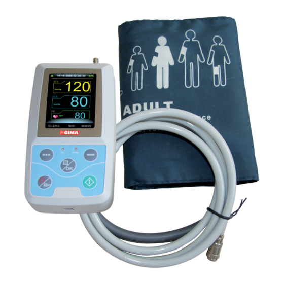
Page 9: Interfaces
1.3 Interfaces For the convenience of operation, the different kinds of interfaces are in different parts of the monitor. At the top is the Socket for SpO Sensor and socket for NIBP cuff 1 the Socket for NIBP cuff 2 the Socket for SpO Sensor Figure 1.3.1 At the bottom is the socket for USB, as shown in Figure 1.3.2. ①the Socket for USB Figure 1.3.2 Bottom 1.4 Accessories... -
Page 10: Chapter 2 Getting Started
The monitor will be supplied with two ‘AA’ alkaline batteries or high capacity. Before using the monitor you shall put the battery in the box of battery. Note When you don’t use the monitor, you will take out the dry battery. 2.3 Power on the monitor Press POWER to power on the monitor. The indicator will flash, the system will enter monitoring screen of monitoring or ABPM, and you can perform normal monitoring now. Refer to System Menu for details. Warning If any sign of damage is detected, or the monitor displays some error messages, do not use it on any patient. Contact biomedical engineer in the hospital or our Customer Service Center immediately. -
Page 11: Connect Oximeter Probe
• System Menu 3.1 Main Interface Press POWER to power on the monitor, The indicator will flash, the system will enter the main interface successfully. ABPM : If there is no key-press operation within the time set in the BACKLIGHT TIME item, the monitor will enter standby mode. RUN indicator light flashes once every other 2 seconds, indicating the monitor is under working mode. Monitoring Mode: BACKLIGHT TIME item setup is of no effect. The backlight is bright all the time. -
Page 12: System Menu
The main interface is shown as the follow: Figure 3.1.1 ABPM main menu Figure 3.1.2 Monitoring main menu Note When the register is full, will be appearance at the top of screen. The note of the last value needs to be cleared. 3.2 System Menu Press the MENU button on the panel to call up the [SYSTEM MENU]. You can perform option operations by using UP and DOWN buttons. -
Page 13: System Setup
Figure 3.2 System menu [PM BP SETUP], [PM SpO SETUP] and [SpO TABLE] are gray in the mode of ABPM. They cannot be set up. 3.2.1 System Setup Select the SYSTEM SETUP item in the [SYSTEM MENU]. The following menu will pop up. Figure 3.2.1 System setup Users can set up the system time by selecting the [TIME] item. -
Page 14: Bp Setup
“dialog box will appear. Select [YES] again will delete the measure record of the last patient, then select [NO] back to the [SYSTEM SETUP MENU]. Else, selecting [NO] at first, the monitor will do nothing. Please pay attention to this function. Users can select PM or ABPM in the [FUNCTION SELECT] item and correspond measures will be taken. In the [BACKLIGHT TIME] item, users can make it from 5 to 120 seconds with 5 seconds per step. Its function is to control the backlight time of the main interface in ABPM. -
Page 15: Spo Setup
The alarm is on or off according to the high and low limits which have been set up. When the pressure higher than the high limit or lower than the low limit, the alarm will occur. [SYS ALM], [MEAN ALM] and [DIA ALM] can be processed separately. The adjustable ranges of the high and low limits of the alarm are as follows: DIA ALM: 40~270 mmHg SYS ALM: 10~215 mmHg MEAN ALM: 20~235 mmHg 3.2.3 Spo SEtuP... -
Page 16: Patient Information
3.2.4 Patient Information Pick the [ABPM INF0] item in the “SYSTEM MENU” to call up the following menu. Figure 3.2.4 ABPM infor The information in this interface can’t be changed, until reinstall the parameter in software. 3.2.5 BP tABLE Pick the [BP TABLE] item in the “SYSTEM MENU” to call up the following menu. Figure 3.2.5.1 NIBP table [total]: the number is the total of all data have been measured from accessing this interface the first time. The sequence number of the current first line will... -
Page 17: Spo
be displayed when changing the data or turning over pages. Every page can contain 10 data at most. Select the [change] item to enter the [Change The Number] menu: Figure 3.2.5.2 Change When the number which you input is more than the total, it will prompt “> total”. Blood pressure measure one time per 5 minutes, and the most number of times is 4896. 3.2.6 Spo tABLE Pick the [SpO TABLE] item in the “SYSTEM MENU” to call up the following menu. Figure 3.2.6.1 table... -
Page 18: Demo Function
[total]: the number is the total of all data have been measured, while accessing this interface for the first time. The sequence number of the first line currently will be displayed, while changing the data or turning over page. Every page can contain 10 data at most. Select the [change] item to enter the [Change The Number] menu: Figure 3.2.6.2 Change When the number which you input is more than the total, it will prompt “>total”. The blood pressure is measured once per 1 s, and the most number of times is 183000. 3.2.7 DEMo function Select the [DEMO] item to enter DEMO status. In the DEMO status, press the “MENU KEY”, and system returns to the “MAIN MENU”. Figure 3.2.7 Demo... -
Page 19: Spo Monitoring
Note In clinical application, this function is forbidden because the DEMO will mislead the medical staff to treat the DEMO waveform and parameter as the actual data of the patient, which may result in the delay of treatment or mistreatment. When it is ambulatory blood pressure state,[PM BP SETUP] [PM SpO SETUP] and [TABLE] can’t be changed in the “MAIN MENU”. Chapter 4 MoNItorING 4.1 What is the Spo2 Monitoring Plethysmogram measurement is employed to determine the oxygen saturation of hemoglobin in the arterial blood. If, for example, 97% hemoglobin molecules in the red blood cells of the arterial blood combine with oxygen, then the blood has a SpO oxygen saturation of 97%. -
Page 20: Precautions During Spo /Pulse Monitoring
Warning ES (Electrosurgery) equipment wire and SpO cable must not be tangled up. Warning Do not put the sensor on extremities with arterial catheter or venous syringe. Note Do not perform SpO measuring and NIBP measuring on same arm at one time, because obstruction of blood flow during NIBP measuring may adversely affect the reading of SpO value. 4.2 Precautions during Spo /Pulse Monitoring Note Make sure the nail covers the light window; ① The wire should be on the backside of the hand. Note waveform is not proportional to the pulse volume. -
Page 21: Maintenance And Cleaning
Figure 4.3 Mounting of the sensor 4.4 Maintenance and Cleaning Care and Cleaning Warning Turn off the monitor before cleaning the monitor or the sensor Warning Do not subject the sensor to autoclaving. Do not immerse the sensor into any liquid. Do not use any sensor or cable that may be damaged or deteriorated. Cleaning: • Use a cotton ball or a soft mull moistened with hospital-grade ethanol to wipe the surface of the sensor, and then dry it with a cloth. This cleaning... -
Page 22: Nibp Monitoring
Warning Prolonged non-invasive blood pressure measurements in Auto mode may be associated with purport, ischemia and neuropathy in the limb wearing the cuff. When monitoring a patient, examine the extremities of the limb frequently for normal color, warmth and sensitivity. If any abnormality is observed, stop the blood pressure measurements. Warning 1. You must not perform NIBP measurements on patients with sickle-cell disease or under any condition which the skin is damaged or expected to be damaged. 2. For a thrombasthemia patient, it is important to determine whether measurement of the blood pressure shall be done automatically. The determination should be based on the clinical evaluation. - Page 23 Note Don’t let the cuff contact with skin directly, but the thickness of clothes shouldn’t be more than 3 cm. Note The width of the cuff should be either 40% of the limb circumference (50% for neonates) or 2/3 of the upper arm length. The inflatable part of the cuff should be long enough to encircle 50-80% of the limb. The wrong size of cuff can cause erroneous readings. If the cuff size is in question, then use a larger cuff.
-
Page 24: Nibp Message And Explanations
5.3 NIBP Message and Explanations Messaggio Spiegazione Causa Self-test failure Probe or A/D sampling error Loose cuff Cuff is not connected correctly Air leakage Air leakage in the valve or airway Atmospheric pressure error Valve cannot be open Signal is too weak Il misuratore non riesce a rilevare la pressione o il bracciale non è allacciato bene. It is over the range Object measuring blood pressure is over the measurement rang Excessive movement When measuring, signal the presence... - Page 25 The cuff can also be machine-washed or hand-washed, the latter method may prolong the service life of the cuff. Before washing, remove the latex rubber bag, and for machine-washing, close the Velcro fastening. Allow the cuff to dry thoroughly after washing, then reinsert the rubber bag. Figure 5.4 Replace Rubber Bag in Cuff To replace the rubber bag in the cuff, first place the bag on top of the cuff so that the rubber tubes line up with the large opening on the long side of the cuff. Now roll the bag lengthwise and insert it into the opening on the long side of the cuff.
-
Page 26: Transportation And Storage
5.5 transportation and storage A. The packed device can be transported by ordinary conveyance or according to transport contract. The device cannot be transported mixed with toxic, harmful, corrosive material. B. The packed device should be stored in room with no corrosive gases and good ventilation. Temperature: -20°C~60°C; Humidity: ≤95% 5.6 Key of Symbols Signal Description Warning – See User Manua l Systolic pressure MEAN MEAN pressure Diastolic pressure %SpO2 The pulse oxygen saturation (%) Pulse rate (bpm) Close the sound Open the alarm sound indication Close the alarm sound indication Type BF Serial number 1. the finger clip falls off (no finger inserted) -
Page 27: Installation Of Software
Display: 17 inch or more CD-ROM Serial port Resolution of printer: 600 DPI 6.2 Installation of Software 1 Place the CD-ROM in the CD-ROM compartment located on your computer. 2 If Auto Play for CDs is enabled, place CD in reader and follow instructions when they appear in the screen; otherwise follow install instructions below: Open Windows Explorer. Click on the root CD-ROM directory. Double click file PM50_Patient_Monitor_V1.2_Setup.exe. - Page 28 Click “Delete” button will delete the current selected user info and configuration. Click “Delete all” Button will delete all users info and their configurations. If you are a new user, click “Okay” Button will appear the following dialog box. Figure 7.1.2 Set file path “Patient File Path”: Choose the downloading route of your case. As soon as the data are downloaded in computer, the case document will save this path. If you check the “Always use default path” checkbox, then data searches will always begin at the default path. If the checkbox is not checked, then data searches will always begin at the last path used.
-
Page 29: The Main Interface
7.2 the main interface When the settings of the user’s configuration information are finished, the main interface is entered, as the following pictured displayed: Figure 7.2 The main operating interface 1. Menu bar - The main operating menu of this software 2. Toolbar - Shortcut keys for functions of frequent use 3. Displaying areas of the trending pictures - After choosing the case which is edited, it is used for displaying the trending picture. 4. -
Page 30: Design The Measurement Plan
1. The device is connected to the computer via the serial port. 2. The device is turned on. Steps: 1. Press the shortcut key , or from the menu select “Upload”, the following dialoga box will appear. Figure 7.4.1 Select the status of the device 2. If the item you choosed is “ABPM” the following dialog box will appear. Figure 7.4.2 Upload test parameters Patient Name, Patient ID: mark the patient. Current Time: That is the time of beginning to collect the parameter. - Page 31 Study Start Time: Collecting start time. It defaulted in the 5 minutes after setting the collecting parameter. Start key: Whether supporting the manual collecting. Time Periods: Among that, Awake refers to the patient in the un-sleeping situation, and Asleep refers to the sleeping situation. Special Start and Special End are optional items. You can set the fixed time to collect the data. Interval setting refers to the intervals of the collecting time. To reduce the impact of the patient’s sleep, settings of the general collecting intervals are longer. Take the above picture as an example: the range of un-sleeping time is 7:00-22:00, the range of sleeping time is 22:00-7:00, the intervals of the un-sleeping time are 5 minutes, and the intervals of the sleeping time are 30 minutes.
-
Page 32: Data Download
The downloaded patient data will be saved in your default computer path. If you want to change the storage path, from the menu select “Download” and the select “Set file path”, and then the dialogue box(Figure 7.1.2) referred before will be showed up, operators can change the path. Press the shortcut key , or from the menu select “Download” and then select “Do Download” will appear the following dialog box. Permiting you select what data you want to download(ABPM data or Patient Monitor data ). Figure 7.5.1 Select the status of the device The following dialog box will appear to show the progress as the data is transferred. Figure 7.5.2 Downloading progress bar After completion, a dialog box will prompt for where the data file was saved. -
Page 33: Delete Data File
Figure 7.6 Patient file select The above dialog box lists the data files found in your current directory. You may use the drive and directory boxes to select a different drive or directory to search for patient files. Select a data file by highlighting the patient’s name, and then press the “Okay” button. You may now edit the data. 7.7 Delete data file If you feel some patient data are not necessary, you can delete them. From menu select “File” and then select “Delete Data” to show patient data delete interface which is similar to patient data select interface, showed as below: Figure 7.7 Data file delete... -
Page 34: Data File Backup
You are able to delete one single file or some files at the same time, to delete some files at the same time; you could push “Ctrl”, and click the file you want to delete at the same time. After selection, click “Okay” button the “sure to delete “ Dialog will appear. Click “ YES” to complete the delete operation. If you want to cancel, please click “NO”. 7.8 Data file backup Sometimes, you may want to save one original copy before you edit a file, under this situation, you should do patient data backup. From the menu select “File” and then select “Copy data”, will appear the following dialog box, permiting you to select which data files to copy. Figure7.8.1 Data file copy Select or deselect items by clicking on the rows using the mouse.When all desired selections have been made, select “Okay”. The following dialog box will appear, permiting you to select the disk drive or directoy to copy to. -
Page 35: Edit Blood Pressure Data
Figure 7.8.2 Backup path settings Once you have selected the destination drive or directory, select “Okay”. You may also select “Cancel” to end the dialog without copying patient data. 7.9 Edit Blood pressure data Press the shortcut key , or from the menu select “Edit” and then select “Bp Data” the following dialog box will pop up. Figure 7.9 Data edit page... -
Page 36: Trend Edit
All the BP readings are shown in the above dialog box. *=7/182 (3.8%): 182 represents the total data sum, 7 represents the data amount deleted, 3.8% stands for data present deleted. Number: stands for data collection serial number. Time: stands for collection time. Date: stands for collection date. BP: number before “/” stands for high blood pressure, number back “/” stands for low blood pressure. PR: Pulse rate. MAP: Mean pressure. PP: Pressure difference between high and low blood pressure. TC: error code (refer to chapter 9) Comment: comment. - Page 37 Figure 7.10.2 Dotted line type BP trend When you move the mouse on the trend area, on the top of the trend area the detail data information about the mouse points will show, including the data serial number, collection time and collection date, high/low blood pressure value, pulse rate, comment, etc. Press mouse’ left button to delete or add the data point to be shown. If the distance between the two data points is too short to move the mouse to one of the points, move the mouse to the time axis area, press the mouse’ left button down, dragging the mouse to the right stretch the BP Trend. Of course you can also dragging the mouse to the left shrink the BP Trend. When you stretching the BP Trend, if the trend length beyond the trend show area will appear a horizontal scroll bar, you can see any part of the trend by changing the scroll bar’s pos.
- Page 38 Figure7.10.4 Shrink BP Trend (time axis) Figure7.10.5 Stretch BP Trend(y-axis) Figure7.10.6 Shrink BP Trend(y-axis)
- Page 39 Trend Edit press the short cut key, will appear the SpO trend interface. Figure 7.10.7 Trend The following picture show different parts of the data area. Move the mouse in the data area, you will see a yellow line, and on top of the data area is the “Selected data info”, where you will see the exact and pulse value according to the time. Along with the mouse move, the value will change accordingly. The SpO and pulse ruler lines show the exact value of the horizontal lines. You can reset these lines by keeping the mouse right button clicked on the “SpO ruler” area or “Pulse ruler” area, and move the mouse.
-
Page 40: Display The Statistics Infomation
Click the “Parameters set” button will appear the following dialog box. Figure 7.10.8 Analysis parameters settings The setup in the dialog box above indicates: (desaturation)event: the SpO value reduces at least 4% while the time keeps at least 10 seconds. Pulse Rate event: the pulse rate fluctuates at least 6bpm while the time keeps at least 8 seconds. 7.11 Display the statistics information Press the shortcut key , or from the menu select “Report” and the select “View Statistics” will pop-up the following dialog box. Figure 7.11 BP statistics information... -
Page 41: Edit Of Diagnose Information
7.12 Edit of diagnose information. Diagnose information including following items: Patient information, Interpretation, Current Medication and Physician information. From the menu select “Edit” and then select “Patient Data” will pop up the following dialog box. Figure7.12 Edit patient’s information click “Current Medications” switch to Current Medications interface, then you can modify the medications for the patient. click “Interpretation” switch to Interpretation interface. click “Physician Info” switch to the page of doctor’s advice. 7.13 Sleep period change Sleep period includes: Awake time and asleep time. Because when collecting patient parameter, patient not always fall asleep and awake according to collection data protocol strictly, you may need change your sleep period. After setup of sleep period, the software... -
Page 42: Bp Thresholds
7.14 BP thresholds After BP Thresholds being set up, the trend graph will renew automaticly, statistic data will be recalculated. From the view select “Edit” and then select “Thresholds” will appear the following dialog box. Figure 7.14 thresholds dialog box The default, recommended thresholds for calculating Blood Pressure Load are 140/90 for awke periods and 120/80 for sleep periods. These are the defaults used when you select the Factory Defaults button. 7.15 histogram Press the shortcut key , will appear the following interface: Figure 7.15... -
Page 43: Piechart
All: Show all BP data statistics. Day: Show only daytime statistics. Night: Show only nighttime statistics. 7.16 Pie chart Press the shortcut key , will appear the following interface: Figure 7.16 Pie chart You can adjust to show the percentage of above normal value, normal value and below normal value. On the left, some statistics can be displayed, such as BP value, PR maximum, minimum, and average value,etc. All: Show all BP data statistics. Day: Show only daytime statistics. Night: Show only nighttime statistics. 7.17 Correlation line Press the shortcut key , will appear the ollowing interface:... -
Page 44: Print Report
Figure 7.17 Correlation line Red line represents systolic; blue line represents diastolic. White small circle represents day time BP value; black small circle represents night time BP value. Histogram Pie chart and Correlation line are useful for your observation about the data. 7.18 Print report After previous data edit, diagnose information edit, trend edit, and so on, the software will create a series of diagnose reports, you can select these pages or some of them for printing. The information of your selection can be saved as default print page for next time. From menu select “Report” and then select “Configure Report” Will appear the following dialog box:... -
Page 45: Appendix
Figure 7.18.1 Configure Report You can select an already exist report for print, you may also click “Edit Report” edit the selected report. Figure 7.18.2 Edit Report You can select all pages or some of them for printing. Only when the data file include SpO data and you checked the “SpO Report” could print SpO report. Click “Title” button, you may enter the title to print at the top of the printed report. -
Page 46: Help
Of course you can also click “Add Report” add a new report. If you don’t need the current report, you can also click “Delete Report” to delete it. The default paper size is: A4, from the menu select “Report” and then select “Select printer”, you can select a printer. From the menu select “Report” and then select “Print preview”, you can preview the page you selected. When you sure you want to print the report, press shortcut key , or from menu select “Report” and then select “Print”. 7.19 help Press shortcut key will pop up help document. Meanwhile, you will find in operation interface; click this button can also active the help document. Chapter 8 trouBLEShootING GuIDE Code Description in Report Editor Solution No signal Check position of cuff, tighten cuff 2 Overreach movement Remain still during BP reading Measurement timeout Check air hose connections and make certain cuff is tight Airway obstructed Check air hose connections and make certain... - Page 48 If the equipment is not disposed of correctly, fines or penalties may be applied in accordance with the national legislation and regulations. GIMA WARRANTY CONDITIONS Congratulations for purchasing a GIMA product.This product meets high qualitative standards both as regards the material and the production. The warranty is valid for 12 months from the date of supply of GIMA. During the period of validity of the warranty, GIMA will repair and/or replace free of charge all the defected parts due to production reasons.
Need help?
Do you have a question about the ABPM and is the answer not in the manual?
Questions and answers