
Related Manuals for Movacolor MC-Balance


Summary of Contents for Movacolor MC-Balance
- Page 1 MC-Balance User Manual 4.0.UK.00 Software version V4.0 Manual revision Date April 2008...
-
Page 3: Table Of Contents
2.1 Safety ________________________________________________________________________________________________ 2 2.2 Certification ____________________________________________________________________________________________ 2 2.3 Operating environmental conditions _________________________________________________________________________ 2 3. Overview Dosing unit ______________________________________________________________________________________ 3 3.1 MC-Balance Component overview __________________________________________________________________________ 3 3.2 Weighing frame _________________________________________________________________________________________ 4 3.3 Motor and dosing system _________________________________________________________________________________ 4 4. Metering principle _________________________________________________________________________________________ 5 5. -
Page 4: Introduction
1. Introduction Thank you for purchasing a Movacolor metering device. This manual is addressed to operators and qualified technicians taking care of the metering of dry additives to ensure correct use of the Movacolor dosing unit. IMPORTANT NOTE: THIS MANUAL MUST BE READ BEFORE INSTALLING THE DOSING UNIT. -
Page 5: General Information
Before switching on the unit for the first time, ensure that the mains power voltage applied is between 80 and 260Vac. Always switch off the Movacolor control cabinet and disconnect the mains power plug from electrical power before performing maintenance. -
Page 6: Overview Dosing Unit
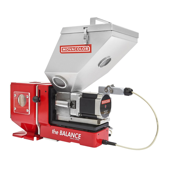
3. Overview Dosing unit 3.1 MC-Balance Component overview Stepper motor Dosing system (Dosing cylinder) Hopper 6 ltr Curled knob M10x40 Standard NST40 Neckpiece Material discharge slide (in closed position) MC-Balance Load frame OPTIONAL Slide frame Slide locking bolt (locking the slide-out position) -
Page 7: Weighing Frame
The motor shaft is equipped with one flat side which fits exact in shaft of the dosing cylinder. To connect the dosing cylinder just put it on the motor axle while turning it to find the flat side, than press the dosing cylinder completely backwards. MC-Balance manual... -
Page 8: Metering Principle
The neckpiece (a mixing chamber) is designed to blend the main material and the additive homogeneously. Movacolor has on stock a large range of machine neckpieces that usually make a prefect fit to the injection molding machine or extruder. -
Page 9: Dosing Systems / Capacities
5. Dosing systems / Capacities Depending on the application a different dosing system might be needed. Use the following table to determine roughly the best system for the application. For more detailed information please contact your agent or Movacolor. Dosing system Granular... - Page 10 All Movacolor dosing units are standard equipped with the stepper motor 2A (LT), in case of using the feed screw A30 the stepper motor 4,5A (HT) will be supplied. Also a screw A20 can be connected to the HT motor.
-
Page 11: Installation
Movacolor cannot be hold liable for any damage during transport. 6.2 Receipt Check the unit thoroughly upon receipt. Pass any remarks to the local agent or Movacolor within 8 days upon receipt of goods. 6.3 Mechanical Installation Most mechanical parts are pre-assembled, making installation quick and simple. -
Page 12: Changing From Dosing Cylinder To Feed Screw
5. Place back the motor + screw by closing the motor quick release clamps. For cleaning the motor + screw can be easily be taken out. POSSIBLE COMBINATIONS GX / GLX / HX Art.nr:H000002 Art.nr:H000014 Included ball bearing G / GL / H Art.nr:H000010 Included seal MC-Balance manual... -
Page 13: Electrical Installation
Abrasive materials o Temperature o Dusty / fine powder materials 6.5 Electrical installation The MC-Balance controller is standard equipped with 3 connections: Mains power cable • Before switching on the unit for the first time, ensure the mains power voltage being applied is between 80 and 260Vac. - Page 14 (See wiring diagram appendix C for electrical connections) 7) POWER SUPPLY The MC-Balance will operate with a voltage from 80 VAC to 260 VAC, 50 and 60 Hz by integrated automatic voltage selector. (See wiring diagram appendix C for electrical connections)
-
Page 15: Operation
Start LED lighted: Scroll through parameters motor is running Mains power switch: ON / OFF Load cell External communication / Network Mains power cable Start input cable Output for: -Alarm -Warning Motor cable Valve output -Running for hopper loader MC-Balance manual... -
Page 16: Start Up & Login
7.2 Start up & Login Directly after switching on the mains power of the MC-Balance, the software versions will be displayed. In the first screen the software version of the terminal will be shown. Movacolor Terminal Version x.xx Date: January 2005 After a few seconds the second screen appears for 10 seconds. -
Page 17: Keyboard Lock
With the keyboard lock ON it is still possible to… Shift between the LOGIN, PRODUCTION and HOPPERLOADER menu. • To START and STOP the dosing unit. • For further information check the Start up & LOGIN paragraph (7.2). MC-Balance manual... -
Page 18: Configuration
7.4 Configuration For initial setup the MC-Balance controller needs to be configured in the CONFIGURATION menu once. Depending on the configuration, some settings will be invisible in case they are not relevant. Highlighted Parameters are factory settings. : ENG / DE... - Page 19 18-30VDC A tacho signal up to 30 Volt DC. This is used when the MC-Balance needs to be connected to an extruder that has a tacho generator that produces a voltage linear to the extruder speed. When using a tacho generator signal, make a connection between the white and brown wire.
- Page 20 The maximum voltage that can be applied to the MC-Balance is 30 VDC. The tacho voltage has to be reduced to 30 VDC if the tacho generator has a higher voltage output than 30 VDC at the maximum extruder output capacity. See the diagram below.
- Page 21 The new voltage is linked to the previous stored speed and the graph will change accordingly. -The maximum voltage that can be applied to the MC-Balance is 30 VDC. -The tacho signal must be a clear signal. Any failure in the voltage signal will be followed by dosing variations.
- Page 22 IP-address for use in a network environment (TCP/IP protocol). (For example 192.168.001.001) When a MC-Balance is part of a network, the controller must have an IP-address for identification. This IP-address has to correspond with the IP-address of your computer. Ask your network administrator for a unique address.
- Page 23 If the controller is used in a Modbus network, the unique identity can be filled in here (1-231) Configuration: Date Actual date (dd / mm / yy) Configuration: Time Actual time (hh / mm / ss) Date and Time will be stored for minimal 1500 hrs. with controller switched OFF. MC-Balance manual...
-
Page 24: Loadcell Calibration
7.5 Loadcell calibration When using a MC-Balance for the first time do an initial load cell calibration as follows: The unit must be mounted horizontally (water leveled) • Avoid vibrations during the load cell calibration. This will influence the calibration. -
Page 25: Material Pre-Calibration
With a pre-calibration it is possible to calibrate the unit before production is started, in this way the time needed to come in spec. can be reduced. The MC-Balance is a gravimetric / loss in weight dosing unit. When starting up the dosing unit for a new production run there is no direct information available about the loss in weight. - Page 26 To clear the material description fill in spaces or select an empty material calibration out of the list. How can I delete or rename a calibrated material? To delete one or more material see chapter 7.13. To delete all Materials select master reset MATERIAL in the CONFIGURATIONS <menu> and confirm. MC-Balance manual...
-
Page 27: Production
Fill in the production settings • Use the arrow buttons to go to Test • Select YES and confirm • The unit will run with the set parameters. • It is possible to stop the test with the stop button. MC-Balance manual... - Page 28 : Count down of the actual dosing time (sec) Speed xxx.x Status : Status of the dosing, Standby / dosing / filling Time xx.x RPM mode needs always a set dosing time, relay function is not functional. Status : Dosing MC-Balance manual...
- Page 29 Act tacho : Actual voltage of the tacho generator (v) nly visible in Tacho mode Act tacho : xxx.x Speed : Actual motor speed (RPM) Speed xxx.x Status : Status of the dosing, Standby / dosing / filling Status : Dosing MC-Balance manual...
-
Page 30: Auto/Manual Regulation Mode & Save Data Function
Starting a new production run with a previous stored material calibration/speed is now possible, PRODUCTION PRODUCTION Regulation mode Fill in material Auto/Manual Description: XXXXXXXX Save data Save data: YES/NO MC-Balance manual... -
Page 31: Production Job
To clear the job description fill in spaces or select an empty job out of the job list. How can I delete or rename a production job? To delete or rename one or more jobs see chapter 7.13 To delete all jobs select master reset JOBS in the CONFIGURATIONS <menu> and confirm. MC-Balance manual... -
Page 32: Filling The Hopper
The controller automatically detects when the hopper is manual filled. In the period that the hopper is being filled, the MC-Balance is dosing with a fixed RPM, this means the unit runs temporarily volumetric. As soon as the hopper filling is ready, the MC-Balance immediately continues to work gravimetric. - Page 33 How the EX (support frame for External hopper loader) works The function of the support frame is to use an foreign hopper loader in combination with the MC-Balance. The support frame is equipped with a knife gate valve for filling the hopper. The valve is normally closed.
- Page 34 Open the hopper lid and fill the hopper by hand. (filling will be detected automatically) The message “Low hopper level” appears when the hopper is empty. (default 700 gr. In CONFIGURATIONS <menu>) ME hopper loader (Movacolor hopper loader operated by compressed air) ME FILLING SYSTEM ME system:...
- Page 35 In the period that the hopper is being filled, the MC-Balance is dosing with a fixed RPM, this means the unit runs temporarily volumetric. As soon as the hopper filling is ready, the MC-Balance immediately continues to work gravimetric.
-
Page 36: Consumption
7.11 Consumption The consumption menu will be visible when an automatic filling system is selected and enabled in HOPPER LOADER <menu>. Without use of the optional Movacolor filling system, accurate working of the consumption registration is not supported. With the Consumption function it is possible to view the total quantity of material dosed by the MC- Balance. -
Page 37: Alarms
To reset an alarm / warning press Stop or the menu button. When an error occurs using the MC-Balance, the display will indicate an error code and description. Together with the displayed error an output contact will be switched. The controller itself gives a beeping signal and the alarm LED will lighten up. - Page 38 “Jobs and curve database initialized” All Jobs and materials are reset - Make new material calibrations and Jobs. Error 13 “Loadcell connection failure” -Load cell connection is not correct. -Load cell connector is not connected to the controller. MC-Balance manual...
-
Page 39: Files
To clear the description fill in spaces or select an empty job out of the list. Search: = Scroll through the files. Delete: = Delete a file, press enter to confirm. Rename: = Rename a file, press enter to confirm. MC-Balance manual... -
Page 40: Event Log
The error codes can be found in paragraph 7.12 EVENT LOG Rec nr: 0078/0078 01/01/06 20:53 Log: COLOR PCT Old: 2.0% New: 1.8% To effectively use the Event Log be aware that the correct data an time must be set in the CONFIGURATION menu. MC-Balance manual... -
Page 41: System Performance
Extreme vibrations and shocks influence system performance noticeably. Normally the system will be able to compensate for vibrations and shocks. The MC-Balance algorithm needs a certain time to weigh material loss and adjust the RPM accordingly. This time depends largely on the set point and the above mentioned two variables. -
Page 42: Trouble Shooting
2. Extreme vibrations and shocks to the system. 3. Check if there is no obstruction to the weighing frame. 4. Check in case of use of an automatic hopper loader if the hoses are connected in the right way. MC-Balance manual... -
Page 43: Appendix A: Mc-Bal. Print View
Flat cable connection between mainboard and load cell board Load cell board rocessor board Incl. Mac-address 2) External terminal connection 8) Identification 3) Connection to PC 4) Inputs 5) Motor 6) Outputs 7) Power supply maninboard version or Network TCP/IP MC-Balance manual... -
Page 44: Appendix B: Mc-Bal. Wiring Diagram
pink green grey brown Load cell connector white green/yellow yellow Version 03 - Valve output for hopper loader (Solid state 24VDC/0.5 A) - Warning output (Solid state 24VDC/0.5 A) - Potential free relay (normally open) output for alarm level (max. 230Vac/30Vdc, 5A) - Potential free relay (normally open) output for running contact (max. -
Page 45: Appendix C: Mc-Bal. Technical Specifications
• Water-cooled flange BH(A) inlet/outlet 50mm/50mm stainless steel ANSI 304. • Water-cooled flange PHA inlet/outlet 100mm/100mm • Hopper loader type ME • Hopper loader type MV • Mixers • External Alarm Flash light. • External Alarm Siren. • MC-Balance manual... -
Page 46: Appendix D: Mc-Bal. Drawings General Dimensions
APPENDIX D: MC-Bal. Drawings General Dimensions General dimension MC-Balance + NST40-Neckpiece MC-Balance manual... - Page 47 General dimension MC-Balance + ME25G + NST40-Neckpiece MC-Balance manual...
- Page 48 General dimension MC-Balance + MV25G + NST40-Neckpiece MC-Balance manual...
- Page 49 General dimension MC-Balance + Support frame + NST40-Neckpiece MC-Balance manual...
Need help?
Do you have a question about the MC-Balance and is the answer not in the manual?
Questions and answers