
Subscribe to Our Youtube Channel
Related Manuals for Wacker Neuson LTV6L


Summary of Contents for Wacker Neuson LTV6L
- Page 1 Operator’s Manual Light Tower LTV6K, LTV6L, LTV8K 60 Hz Type LTV6K, LTV6L, LTV8K Document 5100030216 0317 Date Revision Language 5 1 0 0 0 3 0 2 1 6...
- Page 2 Copyright notice © Copyright 2017 by Wacker Neuson Production Americas LLC All rights, including copying and distribution rights, are reserved. This publication may be photocopied by the original purchaser of the machine. Any other type of reproduction is prohibited without express written permission from Wacker Neuson Production Americas LLC.
-
Page 3: Foreword
Americas LLC will be referred to as Wacker Neuson. ■ Keep a copy of the Operator’s Manual with the machine at all times. ■ For spare parts information, please see your Wacker Neuson Dealer, or visit the Wacker Neuson website at http://www.wackerneuson.com/. - Page 4 ■ Serious injury hazards to the operator and persons in the work area ■ Permanent damage to the machine which will not be covered under warranty Contact your Wacker Neuson dealer immediately if you have questions about approved or unapproved parts, attachments, or modifications.
-
Page 5: Table Of Contents
Table of Contents Foreword Safety Information Signal Words Used in this Manual ............9 Machine Description and Intended Use ..........10 Operating Safety ................11 Metal Halide Lamp Safety ..............13 Service Safety ..................14 Operator Safety while Using Internal Combustion Engines ....16 Safety Guidelines for Lifting the Machine ........... - Page 6 Table of Contents Operation Generator Derating ................52 Control Panels and Receptacles—KUBOTA ........53 Control Panels and Receptacles—KOHLER ........54 Control Panel and Receptacles—DeepSea ........55 Machine Monitoring – DeepSea ............56 Alarms and Shut-Down Conditions – DeepSea ........58 Resetting the Maintenance Timers – DeepSea ........60 Before Starting ..................61 Starting, Operating, Stopping the Machine—KUBOTA .......62 5.10...
- Page 7 12 Emissions Control Systems Information and Warranty: KUBOTA 12.1 Emission Control System Background Information ......102 12.2 Limited Defect Warranty for Wacker Neuson Emission Control Systems .................... 103 13 Emissions Control Systems Information and Warranty: KOHLER 13.1 Emission Control System Background Information ......106 13.2...
- Page 8 Table of Contents wc_bo5100030216_02_FM10TOC.fm...
-
Page 9: Safety Information
Safety Information Safety Information Signal Words Used in this Manual This manual contains DANGER, WARNING, CAUTION, NOTICE, and NOTE signal words which must be followed to reduce the possibility of personal injury, damage to the equipment, or improper service. This is the safety alert symbol. It is used to alert you to potential personal hazards. ►... -
Page 10: Machine Description And Intended Use
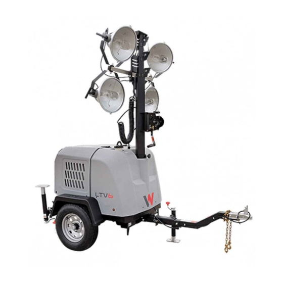
Safety Information Machine Description and Intended Use Machine This machine is a mobile, trailer-mounted light tower. The Wacker Neuson Light description Tower consists of a trailer with a cabinet containing a diesel engine, a fuel tank, a control panel, and an electric alternator. A telescoping tower with four metal halide or LED lights is vertically mounted to the top of the cabinet. -
Page 11: Operating Safety
■ Familiarize yourself with the location and proper use of all controls and safety devices. ■ Contact Wacker Neuson for additional training if necessary. When operating this machine: ■ Do not allow improperly trained people to operate the machine. People operating the machine must be familiar with the potential risks and hazards associated with it. - Page 12 ■ Do not operate the machine if any safety devices or guards are missing or inoperative. ■ Do not modify or defeat the safety devices. ■ Only use accessories or attachments that are approved by Wacker Neuson. Safe When operating this machine: operating ■...
-
Page 13: Metal Halide Lamp Safety
Safety Information ■ The lamps become extremely hot during use! Allow the lamp and fixture to cool 10–15 minutes before handling. Metal Halide Lamp Safety Description The lamps provided with the machine are electric discharge lamps. They are designed for use with metal halide ballasts only, and require time to reach full brightness on initial startup and after a power interruption. -
Page 14: Service Safety
■ Maintenance items that can be performed by the operator are listed in this manual. Other repairs should be performed by a qualified technician. Repairs can be hazardous if not performed correctly. Contact your Wacker Neuson dealer service department for additional information or for repairs to your machine. - Page 15 Safety Information ■ Replace worn or damaged components. Replacing parts and ■ Replace all missing and hard-to-read labels. labels ■ When replacing electrical components, use components that are identical in rating and performance to the original components. ■ When replacement parts are required for this machine, use only Wacker Neuson replacement parts or those parts equivalent to the original in all types of specifications, such as physical dimensions, type, strength, and material.
-
Page 16: Operator Safety While Using Internal Combustion Engines
Safety Information Operator Safety while Using Internal Combustion Engines WARNING Internal combustion engines present special hazards during operation and fueling. Failure to follow the warnings and safety standards could result in severe injury or death. ► Read and follow the warning instructions in the engine owner’s manual and the safety guidelines below. -
Page 17: Safety Guidelines For Lifting The Machine
Safety Information Safety Guidelines for Lifting the Machine When lifting the machine: ■ Make sure slings, chains, hooks, ramps, jacks, forklifts, cranes, hoists, and any other type of lifting device used is attached securely and has enough weight- bearing capacity to lift or hold the machine safely. See chapter Technical Data for machine weight. -
Page 18: Safety Guidelines For Towing The Machine
Safety Information Safety Guidelines for Towing the Machine WARNING Risk of severe injury or death. Improper trailer condition and towing technique can lead to an accident. ► Obey the instructions below to reduce the risk of an accident. When towing the machine: ■... -
Page 19: Reporting Safety Defects
If you believe your trailer has a defect which could cause a crash or could cause injury or death, you should immediately inform the National Highway Traffic Safety Administration (NHTSA) in addition to notifying Wacker Neuson. If NHTSA receives similar complaints, it may open an investigation; and if it finds that a safety defect exists in a group of trailers, it may order a recall and remedy campaign. -
Page 20: Labels
Labels Labels Label Locations wc_gr013742 wc_si001039gb_FM10.fm... - Page 21 Labels wc_gr013743 wc_si001039gb_FM10.fm...
-
Page 22: Label Meanings
Labels Label Meanings DANGER PELIGRO DANGER STOP START 15 SEC. MAX. ARRANQUE 15 SEG. MAX. DEMARRAGE 15 SEC. MAX. WARNING Read and understand the supplied Operator's Manual before operating this machine. Failure to do so increases the risk of injury to yourself and others. ADVERTENCIA Lea y entienda el Manual de Operación suministrado antes de operar esta máquina. - Page 23 Labels See Operator’s Manual for light fixture information and troubleshooting. BEFORE STARTING THE ENGINE: 1. Check levels of: ■ Engine oil ■ Fuel ■ Coolant 2. Move the circuit breakers to the OFF position. TO START THE ENGINE: 1. On the engine control panel, turn the key switch to the PREHEAT position; the indicator light will illuminate during preheating.
- Page 24 Labels DANGER Contact with overhead electrical power lines will cause serious injury or death. Do not position Light Tower under electrical power lines. WARNING Ultraviolet radiation from lamp can cause serious skin and eye irritation. Use only with undamaged lamps. Use only with provided undamaged lens cover and fixture.
- Page 25 Labels Manual Winch TO RAISE TOWER 1. Lift pins and extend outriggers 2. Raise tower with winch. 3. Loosen mast rotation knob to aim tower. Tighten knob when tower is aimed. TO LOWER TOWER 1. Turn off breakers and engine. 2.
- Page 26 Labels WARNING ADVERTENCIA AVERTISSEMENT WARNING 85 lb-ft ADVERTENCIA 115 Nm AVERTISSEMENT 5100031166 WARNING ADVERTENCIA AVERTISSEMENT WARNING 85 lb-ft ADVERTENCIA 115 Nm AVERTISSEMENT 5100031252 WARNING (On trailer, if equipped) Lights can prevent trailer from being hit by other vehicles. You must: 1.
- Page 27 Labels WARNING ADVERTENCIA 839 kg (1850 LBS) AVERTISSEMENT WARNING ADVERTENCIA AVERTISSEMENT 5100031165 WARNING ADVERTENCIA 839 kg AVERTISSEMENT (1850 LBS) WARNING ADVERTENCIA AVERTISSEMENT 5100031251 WARNING (On trailer, if equipped) Uncoupling will cause trailer to come loose from tow vehicle. You must: 1.
- Page 28 Labels WARNING WARNING Electric shock and arc flash can cause serious injury or Electric shock and arc flash can cause serious injury or death. Electrical storage device death. Electrical storage device within. Contact a within. Contact a qualified electrician for service or to open electrical box.
- Page 29 Labels WARNING WARNING WARNING Explosion hazard. ADVERTENCIA ADVERTENCIA ■ Do not use evaporative starting fluids such as ether AVERTISSEMENT AVERTISSEMENT on this engine. 5200005890 5200005890 ■ The engine is equipped with a cold starting aid. Using evaporative starting fluids can cause an explosion which can cause engine damage, personal injury, or death.
-
Page 30: Lifting And Transporting
Lifting and Transporting Lifting and Transporting Lifting the Machine ■ Properly rated lifting equipment (crane or hoist). See Chapter Technical Data. Requirements ■ Machine stopped. ■ All doors and access covers closed and secured. ■ Tower is completely lowered. ■ The winch (e) and lights are facing foward. ■... -
Page 31: Preparing The Machine For Transport On A Truck Or Trailer
Lifting and Transporting Preparing the Machine for Transport on a Truck or Trailer ■ Machine stopped. Requirements ■ Flatbed truck or trailer capable of supporting the machine’s weight. ■ Chains, hooks, or straps capable of supporting the machine’s weight. WARNING Crushing hazard. -
Page 32: Before Towing Checklist
Lifting and Transporting Before Towing Checklist For trailer machines only. Before towing the machine, check the licensing requirements for trailers in your area. Check the following items: Machine All doors and access panels of the machine are closed. All electrical connections are disconnected from the machine. ... -
Page 33: Towing The Machine
Loss of wheels can cause an accident, severe injury or death. ► Tighten the lug nuts to the proper torque before towing the machine. NOTICE: Wacker Neuson recommends a maximum towing speed of 88 km/h (55 mph) on highways and paved roads and 16 km/h (10 mph) on rugged roads and terrain. -
Page 34: Trailer
Lifting and Transporting Trailer Background The machine’s trailer is equipped with safety chains (a), tongue jack (b), lights, and a coupler (pintle or ball-type) (c). wc_gr011629 ■ In most states, large trailers must be registered and licensed by the State Licensing requirements Department of Transportation. -
Page 35: Flip-Up Tongue
Lifting and Transporting Flip-up Tongue Background The flip-up tongue allows the machine to be stored in a smaller space than a machine with a conventional tongue. Procedure Perform the procedure below to raise the flip-up tongue to the storage position. 1. -
Page 36: Machine Setup
1. Make sure all loose packaging materials have been removed from the machine. 2. Check the machine and its components for damage. If there is visible damage, do not operate the machine! Contact your Wacker Neuson dealer immediately for assistance. -
Page 37: Positioning The Machine
► Do not operate the machine near flammable vapors, fuels, or combustibles. CO Alarms Because this machine produces carbon monoxide (CO), Wacker Neuson recommends that CO alarms be installed in all structures in close proximity to the machine. CO alarms provide an extra measure of protection against this poison that you cannot see or smell. -
Page 38: Ground Connection
Machine Setup Ground Connection Location A ground connection (a) is located on the trailer frame. wc_gr013762 Function This ground connection is used for electrically grounding the Light Tower when necessary to comply with the National Electrical Code and other federal, state, and local regulations. -
Page 39: Leveling The Trailer-Vertical Mast Light Towers
Machine Setup Leveling the Trailer—Vertical Mast Light Towers WARNING Tipping and falling hazard. Failure to level the trailer or extend the outriggers will reduce the stability of the unit. ► Level the trailer and extend the outriggers before raising the tower. The outriggers must remain extended while the tower is up. -
Page 40: Refueling The Machine
Machine Setup Refueling the Machine ■ Machine shut down Requirements ■ Engine cool ■ Machine/fuel tank level with the ground ■ Fresh, clean fuel supply Procedure Perform the procedure below to refuel the machine. WARNING Fire hazard. Fuel and its vapors are extremely flammable. Burning fuel can cause severe burns. -
Page 41: Aiming The Lights-Vertical Mast Light Towers
Machine Setup Aiming the Lights—Vertical Mast Light Towers ■ Each individual light fixture can be independently aimed up, down, left, or right. Overview There are four total light fixtures on each machine. ■ This procedure is not for rotating the lights as a single unit while the tower is raised. - Page 42 Machine Setup Continued from the previous page. Aiming Left or Right 1. Grasp the light fixture and aim it to the left or right. If necessary, loosen the bracket nut (c) to allow movement of the fixture. NOTICE: Do not loosen the nut (b). Damage to the light fixture may occur. wc_gr013747 2.
-
Page 43: Manually Rotating The Light Bar
Machine Setup Manually Rotating the Light Bar Overview The operator can rotate the light bar 360° while the tower is lowered. Procedure Perform the procedure below to rotate the light bar. 1. Loosen out the locking knob (a). wc_gr013767 2. Rotate the light bar to the desired position. 3. -
Page 44: Raising The Tower-Manual Winch System
Machine Setup Raising the Tower—Manual Winch System Background The Light Tower includes a telescoping winch for raising the tower. The winch is an automatic brake-type winch that automatically brakes when the handle is released. The handle must be rotated to wind in the cable as well as to unwind the cable. ■... - Page 45 Machine Setup Continued from the previous page. Reference graphic wc_gr013770 Procedure Perform the procedure below to raise the tower. ■ Do not attempt to raise the tower if the winch is damaged or not operating NOTICES properly, or if the winch cables are worn or damaged. ■...
-
Page 46: Lowering The Tower-Manual Winch System
Machine Setup Lowering the Tower—Manual Winch System ■ Lights are turned off Requirements ■ Engine is stopped ■ Outriggers are extended and locked in place WARNING Tipping/falling hazards. Certain actions may cause the tower to fall or the machine to tip over. ►... - Page 47 Machine Setup Continued from the previous page. 2. If the light bar has been rotated, loosen the locking knob (b) and rotate the tower so the light bar and winch are facing toward the trailer tongue. See topic Manually Rotating the Light Bar. 3.
-
Page 48: Raising The Tower-Power Winch System
Machine Setup 4.10 Raising the Tower—Power Winch System Background The Light Tower includes a telescoping winch for raising the tower. ■ Machine is shut down Requirements ■ Light Tower is located on a firm, flat surface clear of overhead wires and obstructions ■... - Page 49 Machine Setup Continued from the previous page. Procedure Perform the procedure below to raise the tower. ■ Do not attempt to raise the tower if the winch is damaged or not operating NOTICES properly, or if the winch cables are worn or damaged. ■...
-
Page 50: Lowering The Tower-Power Winch System
Machine Setup 4.11 Lowering the Tower—Power Winch System ■ Lights are turned off Requirements ■ Engine is stopped ■ Outriggers are extended and locked in place WARNING Tipping/falling hazards. Certain actions may cause the tower to fall or the machine to tip over. - Page 51 Machine Setup Continued from the previous page. 2. If the light bar has been rotated, loosen the locking knob (a) and rotate the tower so the light bar and winch are facing toward the trailer tongue. See topic Manually Rotating the Light Bar. 3.
-
Page 52: Operation
Operation Operation Generator Derating Description All generator sets are subject to derating (reduced power output) depending on the altitude and ambient temperature. Derating should not affect the operation of the floodlights, although it will reduce the available reserve power to the receptacle. Derating Power ratings are typically reduced by the following percentages: percentages... -
Page 53: Control Panels And Receptacles-Kubota
Operation Control Panels and Receptacles—KUBOTA wc_gr013749 Ref. Description Ref. Description 33A main circuit breaker (8K) Shore power switch 50A main circuit breaker (6K) (optional for 6K) 33A GFI circuit breaker (8K) Control panel light 25A GFI circuit breaker (6K) 30A lights circuit breaker 30A receptacle breaker (standard for 8K) Tower winch rotary switch (optional) -
Page 54: Control Panels And Receptacles-Kohler
Operation Control Panels and Receptacles—KOHLER wc_gr013750 Ref. Description Ref. Description Low fuel indicator (not used) Tower winch rotary switch (optional) Safety shut-down indicator 20A GFI circuit breakers (optional) Low oil pressure shut-down Air filter restriction indicator indicator High coolant temperature shut- Auxiliary lights (not used) down indicator Alternator indicator... -
Page 55: Control Panel And Receptacles-Deepsea
Operation Control Panel and Receptacles—DeepSea wc_gr013748 Ref. Description Ref. Description Menu navigation buttons (up/down) Auto start button Controller display Start button 25A main circuit breaker (6K) Hour meter 33A main circuit breaker (8K) 20A GFI circuit breaker Control panel light 30A lights circuit breaker 30A receptacle breaker (standard for 8K) -
Page 56: Machine Monitoring - Deepsea
Operation Machine Monitoring – DeepSea Description Engine and generator information is displayed on the the LCD panel The user can scroll through the screens to monitor machine parameters. Volts “V”- Displays the AC output voltage being produced by the generator. wc_gr012363 Volts “V”- Displays the AC output voltage being produced by the generator. - Page 57 Operation Displays the available voltage of the battery. wc_gr012357 Displays the maintenance interval as well as the time remaining until maintenance is required. Each parameter is displayed on a separate screen: ■ Oil change ■ Air filter ■ Fuel filter wc_gr012360 wc_tx004431gb_FM10.fm...
-
Page 58: Alarms And Shut-Down Conditions - Deepsea
Operation Alarms and Shut-Down Conditions – DeepSea Background The Light Tower controller monitors variables of engine and machine function. The Light Tower controller has two types of alarms: warning alarms and shut-down alarms. Warning Warnings are non-critical alarm alarms conditions that do not affect the operation of the generator system. - Page 59 Operation Continued from the previous page. Alarm and Shutdown limits Variable Normal Warning Shutdown To Reset Overspeed 60 Hz 63 Hz 66 Hz Press “Stop”. Underspeed 60 Hz 57 Hz 55 Hz Press “Stop”. Overcrank — — After 3 attempts Press “Stop”.
-
Page 60: Resetting The Maintenance Timers - Deepsea
Operation Resetting the Maintenance Timers – DeepSea Background The maintenance timers are preset on the controller. When the timer expires, the alarm will display in the upper right corner of the screen. The maintenance timers are preset as follows: ■ Oil change interval: 750 hours ■... -
Page 61: Before Starting
Operation Before Starting Before putting the Light Tower into service, review each item on the following checklist. Light Towers often run unattended for long periods of time. Therefore, it is important to make sure that the machine is set up properly to avoid possible operating problems. -
Page 62: Starting, Operating, Stopping The Machine-Kubota
Operation Starting, Operating, Stopping the Machine—KUBOTA ■ Before starting checks completed. See topic Before Starting. Requirements ■ Electrical cables in good condition with no cuts or abrasions in the insulation. ■ Circuit breakers (a, b, c, and d, g for 8K) are in the OFF position. ■... - Page 63 Operation Continued from the previous page. Operating the Perform the procedure below to operate the lights. lights 1. Turn on the main circuit breaker (a). wc_gr013751 2. Turn on individual circuit breakers (c) one at a time. ■ Metal halide floodlights require a warm-up time of 5–15 minutes before they Notes reach full brightness.
-
Page 64: Starting, Operating, And Stopping The Machine-Kohler
Operation 5.10 Starting, Operating, and Stopping the Machine—KOHLER Requirements Check the following items before starting the machine. ■ Before starting checks completed. See topic Before Starting. ■ Electrical cables are in good condition with no cuts or abrasions in the insulation. - Page 65 Operation Continued from the previous page. Operating the Perform the procedure below to operate the lights. lights 1. Turn on the main circuit breaker (a). wc_gr013753 2. Turn on individual circuit breakers (c) one at a time. ■ Metal halide floodlights require a warm-up time of 5–15 minutes before they Notes reach full brightness.
-
Page 66: Starting, Operating, Stopping The Machine-Deepsea
Operation 5.11 Starting, Operating, Stopping the Machine—DeepSea ■ Before starting checks completed. See topic Before Starting. Prerequisites ■ Electrical cables in good condition with no cuts or abrasions in the insulation. ■ Circuit breakers (a, b, c and d, h for 8K) are in the OFF position. ■... - Page 67 Operation Continued from the previous page. Operating the Perform the procedure below to operate the lights. lights 1. Turn on the main circuit breaker (a). wc_gr013779 2. Turn on individual circuit breakers (c) one at a time. ■ Metal halide floodlights require a warm-up time of 5–15 minutes before they Notes reach full brightness.
-
Page 68: Auto Mode (Remote Run)
Operation 5.12 Auto Mode (Remote Run) The engine controller is capable of automatically starting the engine. A scheduled run will begin only if the controller is in Auto Mode with no shut-down alarm present. If the controller is in Stop/Reset Mode or Manual/Start Mode when a scheduled run begins, the engine will not start. - Page 69 Operation 3. Press “Auto” to enter the selected editor. Note: If a PIN code has been set for the Configuration Editor, the PIN request appears. 4. Press the up and down arrows to adjust first digit to the correct value. 5.
-
Page 70: Engine - Jump-Starting
Operation Scheduler (3) Duration 0:00:00 Scheduler (4) Start Time 0:00:00 Scheduler (4) Start Day 0 (1=Monday) Scheduler (4) Start Week 1,2,3,4 Scheduler (4) Duration 0:00:00 Scheduler (5) Start Time 0:00:00 Scheduler (5) Start Day 0 (1=Monday) Scheduler (5) Start Week 1,2,3,4 Scheduler (5) Duration 0:00:00... - Page 71 Operation WARNING Battery fluid is poisonous and corrosive. ► In the event of ingestion or contact with skin or eyes, seek medical attention immediately. NOTICE: Observe the following precautions to prevent serious damage to the electrical system. Jump-starting a shorted or defective battery will cause the voltage regulator to supply higher than normal voltage.
- Page 72 Operation 6. Start the engine on the machine that is being used as a power source. 7. Wait for a minimum of two minutes while the battery in the stalled machine partially charges. 8. Turn the engine key switch and hold it until the engine starts. NOTICE: Cranking the engine for more than five seconds can cause starter damage.
-
Page 73: Emergency Shutdown Procedure
Operation 5.14 Emergency Shutdown Procedure General Perform the procedure below if a breakdown or accident occurs while the machine procedures is operating: 1. Stop the engine. 2. Disconnect all loads from the machine. 3. Lower the tower. 4. Allow the machine to cool before opening the cabinet. 5. -
Page 74: Using The Convenience Receptacles-60 Hz
Operation 5.15 Using the Convenience Receptacles—60 Hz Description This machine is equipped with one or more convenience receptacles (a) for running accessories and tools from the generator. Each receptacle is protected by its own circuit breaker (b). Power to the receptacle(s) is available any time the engine is running and the circuit breaker is set to the ON position. -
Page 75: Factory-Installed Options
This machine may be equipped with one or more of the following factory-installed options. To verify if any of these options are installed on your machine, contact Wacker Neuson Corporation at 1-800-770-0957. A nameplate listing the Model Number, Item Number, Revision, and Serial Number is attached to each unit. -
Page 76: Battery Blanket
Factory-Installed Options Battery Blanket An electrically powered blanket (a) warms the battery while the machine is not in use. The blanket eliminates engine starting difficulties caused by a cold or frozen battery. Plug the cord into a 120V power supply. wc_gr007422 Oil Pan Heater Cold, thick engine oil does not flow freely and may cause engine starting... -
Page 77: Fuel And Water Separator
Factory-Installed Options Fuel and Water Separator The fuel and water separator (a) removes water from the fuel supply. As fuel flows through the separator element, removed water collects in the bowl. wc_gr013983 Positive Air Shutoff Description Diesel engines may occasionally continue to run even after the machine has been turned off. -
Page 78: General Maintenance
General Maintenance General Maintenance WARNING A poorly maintained machine can malfunction, causing injuries or permanent damage to the machine. ► Keep the machine in safe operating condition by performing periodic maintenance and making repairs as needed. Preparing for Maintenance Do not perform even routine service (oil/filter changes, cleaning, etc.) unless all electrical components are shut down. -
Page 79: Periodic Maintenance Schedule
General Maintenance Periodic Maintenance Schedule The table below lists basic machine maintenance. Tasks designated with check marks may be performed by the operator. Tasks designated with square bullet points require special training and equipment. Every Every Every Daily 250 hours 500 hours 1000 hours before... -
Page 80: Cleaning The Machine
General Maintenance Cleaning the Machine When As needed ■ Clean water supply Requirements ■ Mild detergent ■ Clean, dry cloths NOTICE: Do not use a pressure washer to clean this machine. Pressurized water can severely damage the generator and sensitive electronic components. Interior Clean the interior of the machine. -
Page 81: Maintaining The Trailer
General Maintenance Maintaining the Trailer ■ Keep the tires inflated to the proper pressure as shown on the tire sidewall. Tires ■ Check tire tread periodically for wear. ■ Replace the tires as required. ■ Check that the lug nuts holding the wheels are tight. Wheels ■... -
Page 82: Maintaining The Battery
General Maintenance Maintaining the Battery WARNING Explosion hazard. Batteries can emit explosive hydrogen gas. ► Keep all sparks and flames away from the battery. ► Do not short-circuit battery posts. Safety Observe the following safety precautions to prevent serious damage to the precautions electrical system. -
Page 83: Removing And Replacing Lamps
General Maintenance Removing and Replacing Lamps ■ Engine shut down Requirements ■ Light circuit breakers turned OFF ■ Lamps and fixtures cool to the touch ■ Eye and hand protection WARNING Burn hazard. Lamps become extremely hot in use. ► Allow lamps and fixtures to cool 10–15 minutes before handling. WARNING Personal injury hazard. - Page 84 General Maintenance Continued from the previous page. Perform the procedures below to remove and install the lamp. Removing the 1. Remove the screws (a) securing the flange rings (b) and remove the flange lamp rings. wc_gr005881 2. Remove the lens (c) with the gasket (d) attached. 3.
-
Page 85: Long-Term Storage
General Maintenance Long-Term Storage Introduction Extended storage of equipment requires preventive maintenance. Performing these steps helps to preserve machine components and ensures the machine will be ready for future use. While not all of these steps necessarily apply to this machine, the basic procedures remain the same. -
Page 86: Machine Disposal And Decommissioning
General Maintenance Machine Disposal and Decommissioning Introduction This machine must be properly decommissioned at the end of its service life. Responsible disposal of recyclable components, such as plastic and metal, ensures that these materials can be reused—conserving landfill space and valuable natural resources. -
Page 87: Engine Maintenance: Kubota D1005 / D1105
Engine Maintenance: Kubota D1005 / D1105 Engine Maintenance: Kubota D1005 / D1105 The information in this chapter comes from copyrighted Kubota material. The viscosity of the engine oil is an important factor when determining the correct engine oil to use in your machine. Use an engine oil of appropriate viscosity based on the expected outside air temperature. - Page 88 Engine Maintenance: Kubota D1005 / D1105 The engine maintenance schedule(s) in this chapter are reproduced from the engine owner’s manual. For additional information, see the engine owner’s manual. SERVICE INTERVALS Observe the following for service and maintenance. Interval Item Every 50 hours Check of fuel pipes and clamp bands See NOTE Change of engine oil...
- Page 89 Engine Maintenance: Kubota D1005 / D1105 The jobs indicated by must be done after the first 50 hours of operation. 1 Air cleaner should be cleaned more often in dusty conditions than in normal conditions. 2 After 6 times of cleaning. 3 Consult your local KUBOTA Dealer for this service.
-
Page 90: Engine Maintenance: Kohler
Engine Maintenance: KOHLER Engine Maintenance: KOHLER The information in this chapter comes from copyrighted Kohler material. The viscosity of the engine oil is an important factor when determining the correct engine oil to use in your machine. Use an engine oil of appropriate viscosity based on the expected outside air temperature. - Page 91 Engine Maintenance: KOHLER wc_tx004459gb_FM10.fm...
- Page 92 Engine Maintenance: KOHLER The engine maintenance schedule(s) in this chapter are reproduced from the engine owner’s manual. For additional information, see the engine owner’s manual. wc_tx004459gb_FM10.fm...
- Page 93 Engine Maintenance: KOHLER wc_tx004459gb_FM10.fm...
- Page 94 Engine Maintenance: KOHLER wc_tx004459gb_FM10.fm...
-
Page 95: 10 Troubleshooting
Fuel circuit failure Check fuel lines. No generator output Main circuit breaker open Close main circuit breaker. Voltage regulator malfunction Call Wacker Neuson for service. Low oil pressure Low oil level Fill engine sump with oil. Clogged oil filter Replace oil filter. - Page 96 Troubleshooting Problem Cause Remedy Lamp will not light Lamp is too hot Allow lamp to cool 10–15 minutes before restarting. Faulty lamp connection Check that lamp is tight in socket. Check connections inside connection boxes on light fixtures and tower. Plug connection at fixture is loose or Repair or replace the plug connection.
-
Page 97: 11 Technical Data
Technical Data 11 Technical Data 11.1 Engine—KUBOTA Engine Power Rating Net power rating per ISO 3046 IFN. Actual power output may vary due to conditions of specific use. Machine LTV6K LTV8K Engine Make Kubota Model D1005 D1105 Type 3-cylinder, 4-cycle, liquid-cooled diesel Max. -
Page 98: Engine-Kohler
Technical Data 11.2 Engine—KOHLER Engine Power Rating Net power rating per ISO 3046 IFN. Actual power output may vary due to conditions of specific use. Machine LTV6L Engine Make Kohler Model LDW1003 Type 3-cylinder, 4-cycle, liquid-cooled diesel Max. power rating @ rated kW (hp) 8.0 (10.7) @ 1800 rpm... -
Page 99: Generator
Technical Data 11.3 Generator Machine: LTV6 LTV8 Frequency Continuous output Output volts/phase 120/240, 1Ø (6K) 120/240, 1Ø 120, 1Ø (6L) Amps 50/25 66/33 Excitation type Capacitor / Brushless Power factor Voltage regulation - No load ± 6.0 to full load Speed (no-load) 1800 wc_tx004432gb_FM10.fm... -
Page 100: Machine
Technical Data 11.4 Machine LTV6K LTV6L LTV8K Model Unit LTV6K LTV6L (C.W.) LTV8K (C.W.) Dimensions 256 X 146 X 251 256 X 146 X 251 256 X 146 X 251 (L x W x H) (in) (101 X 58 X 99) -
Page 101: Radiation Compliance
These lamps comply with FDA regulation performance standards 21 CFR 1040-30. 11.6 Dimensions—LTV6K, LTV8K, LTV6L 251 cm (99 in) 147 cm... -
Page 102: 12 Emissions Control Systems Information And Warranty: Kubota
Tampering and Altering Tampering with or altering the emission control system may increase emissions beyond the legal limit. If evidence of tampering is found, Wacker Neuson may deny a warranty claim. Among those acts that constitute tampering are: ■ Removing or altering of any part of the air intake, fuel, or exhaust systems. -
Page 103: Limited Defect Warranty For Wacker Neuson Emission Control Systems
What is covered Wacker Neuson recommends the use of genuine Wacker Neuson parts, or the equivalent, whenever maintenance is performed. The use of replacement parts not equivalent to the original parts may impair the effectiveness of the engine/ equipment emission controls systems. - Page 104 The engine/equipment must be presented to an authorized Wacker Neuson dealer/ service center as soon as a problem exists. Contact Wacker Neuson Product Support Department (1-800-770-0957) or visit wackerneuson.com to find a dealer/ service center in your area, or to answer questions regarding warranty rights and responsibilities.
- Page 105 For owners located more than 100 miles from an authorized dealer/service center (excluding the states with high-altitude areas as identified in 40 CFR Part 1068, Appendix III), Wacker Neuson will pay for pre-approved shipping costs to and from an authorized Wacker Neuson dealer/service center.
-
Page 106: 13 Emissions Control Systems Information And Warranty: Kohler
Tampering and Altering Tampering with or altering the emission control system may increase emissions beyond the legal limit. If evidence of tampering is found, Wacker Neuson may deny a warranty claim. Among those acts that constitute tampering are: ■ Removing or altering of any part of the air intake, fuel, or exhaust systems. -
Page 107: Limited Defect Warranty For Exhaust Emission Control System
Emissions Control Systems Information and Warranty 13.2 Limited Defect Warranty for Exhaust Emission Control System See the supplied engine owner’s manual for the applicable emission warranty statement. wc_tx004144gb_FM10.fm... - Page 109 Wacker Neuson Production Americas LLC, N92W15000 Anthony Ave., Menomonee Falls, WI. 53051 Tel.: (262) 255-0500 Fax: (262) 255-0550 Tel.: (800) 770-0957 Wacker Neuson Limited - Room 1701–03 & 1717–20, 17/F. Tower 1, Grand Century Place, 193 Prince Edward Road West, Mongkok, Kowloon, Hongkong. Tel: (852) 3605 5360, Fax: (852) 2758 0032...
Need help?
Do you have a question about the LTV6L and is the answer not in the manual?
Questions and answers
Parts manual for LTV6L
You can find the parts manual for the Wacker Neuson LTV6L on the Wacker Neuson website at [http://www.wackerneuson.com/](http://www.wackerneuson.com/) or by visiting an authorized Wacker Neuson dealer.
This answer is automatically generated