
Related Manuals for Strong TrussTrouper 1.2

Summary of Contents for Strong TrussTrouper 1.2
- Page 1 FOLLOW SPOTLIGHT INSTRUCTION MANUAL TrussTrouper 1.2 • Equipment Type 41080 Rev. August 2007 4350 McKinley Street • Omaha, Nebraska 68112 USA Tel (402) 453-4444 • Fax (402) 453-7238 • www.strong-lighting.com...
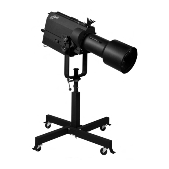
- Page 3 The bulb has an expected life of (500) hours of operation, and it is advis- able to have a spare bulb available for each unit. THE SPOTLIGHT is shipped with a yoke adaptable for truss mounting. An optional folding floor stand assembly or tripod base are available through Strong International Dealers. Interchangeable lens mechanisms are supplied in Long, Medium and Short throw configurations, and are readily mounted to the TrussTrouper as the application or venue requires.
- Page 4 INSTALLATION - OPERATION INSPECT THE UNIT upon receipt. Any damage must be reported to the freight car- rier immediately. It is the responsibility of the consignee, not the shipper, to file damage claims. THE HMI BULB, if ordered with the unit, is included in the accessory kit packed with the spotlight.
-
Page 5: Maintenance
ELECTRICAL CONNECTION for the 41080-01 or -02 (120 V.AC, 60 Hz.) requires a 120 V.AC, three prong 15 ampere grounded outlet. The Type 41080-03 or -04 (240 V.AC, 50/60 Hz.) may be fitted with a plug acceptable for the local electrical supply. See the Equipment Data Plate for the correct voltage before connecting the unit. Sustaining line draw of the TrussTrouper is (12) amperes;... - Page 6 OPERATION OF OPTICAL SYSTEM THE OPTICAL SYSTEM of the TrussTrouper consists of a spot size selector, an iris assembly to reduce the size of the spot aperture, and a fade-out chopper assembly to permit reducing light output from full intensity to complete douse. The iris and chopper controls are mounted on the back of the lamphouse and are fully accessible from either side of the unit. The spot size is selected by setting and locking a control knob located on the right side (as viewed from rear) of the unit.
- Page 7 OPERATION OF COLOR BOOMERANG THE COLOR BOOMERANG is equipped with six color holders. Additional filter holders can be supplied by an authorized Strong International Dealer. TO OPERATE INDIVIDUAL COLOR FILTERS, engage the desired filter selector lever. A rocker catch located in the color disc housing holds the filter in position.
- Page 8 TrussTrouper 1.2 Wiring Diagram 110-120 V.AC 208-230 V.AC Neutral Phase Grnd Grnd 1200 Watt HMI 1200 Watt HMI NOTE: Lamp “On” when X9 open Lamp “Off” when X9 shorted Wire S2 switch across COM & N.C. TT/06...
-
Page 9: Wiring Diagram
WIRING DIAGRAM Parts List Ref. Desig. Part No. Description B1,2 61-98002 Blower, 115 V.AC, 50/60 Hz. 81272 Blower, 230 V.AC, 50/60 Hz. (early Export units) 88253 Blower Power Cord & Plug 41103 HMI Bulb, 1200 Watt M1 31-32001 Elapsed Time Meter 71660 Switching Circuit Breaker, 16 A. 31-61011 Interlock Switch, Pushbutton 21-61228... - Page 10 TT/08...
- Page 11 FIGURE 1 Parts List Description Item Part No. 25396 Screw, 10-32 Captive 2 81-28002 Hand Rail 4257102 Washer, Hand Rail 41908 Rear Panel (Welded to Item 6) 4268006 Hand Rail Fastening Nut, 1/4-28 Hex 41908 Lamphouse Cover, Welded Assembly (incl. Item 4) 41315 Bottom Cover, Welded Assembly 11-40037 AC Power Cord...
- Page 12 TT/10...
- Page 13 FIGURE 2 Parts List Description Item Part No. 41257 Bulb Contact 41254 Upper Bulb Retainer 41300 Reflector 4081002 Mounting Screw, 8-32 x 1" Pan Head 41-35008 Spacer 41907 Bulb Mounting Pedestal 4060370 Mounting Screw, 6-32 x 3/8" Pan Head 41103 HMI Bulb, 1200 Watt Double-Ended 4080310 Mounting Screw, 8-32 x 5/16"...
- Page 14 FIGURE 2 Parts List (continued) Description Item Part No. 41264 Iris Spacer Plate 41265 Lens Retaining Ring 41302 Condensor Lens 41281 Condensor Lens Mounting Ring 34 41277 Lens Ring Guide Rod 41271 Phenolic Bushing 48103 Knob, Red Plastic - 41370 Threaded Shaft 4257102 Flatwasher, 1/4" 41229 Slide Bar 41275...
- Page 15 FIGURE 2 Parts List (continued) Description Item Part No. 51168 Knurled Knob, Bulb Positioning Control (3 req’d.) 4080184 Set Screw, 8-32 x 3/16" 41336 Spacer, Bulb Adjustment (3 req’d.) 25387 Balance Slide Bracket (2 req’d.) 41227 Switch Mounting Bracket 21-61228 Rocker Switch (S3), LAMP ON/OFF 71660 Switching Circuit Breaker (S1), POWER 41283...
- Page 16 FIGURE 3 COLOR BOOMERANG Assembly No. 25419 Description Item Part No. 45308 Color Release Pushbutton 41239 Boomerang Cover Plate 45306 Pivot Stud Bushing 4253500 Pivot Stud Bolt, 1/4-20 x 3-1/2" 01704 Hitch Pin (4 req’d.) 4087101 Washer (12 req’d.) 7 18122 Retainer Plate, Rear 51-58029 Compression Spring...
- Page 17 FIGURE 3 Parts List (continued) Description Item Part No. 17 18121 Retainer Plate, Front 4258015 Nylon Hexnut, 1/4-20 (2 req’d.) 4257001 Shakeproof Lockwasher, 1/4" 45308 Hook (early models only) 46150 Clip (3 req’d. per Color Holder) 4040250 Screw, 4-40 x 1/4" (2 req’d. per Color Holder) 18118 Color Frame (2 req’d.
- Page 18 FIGURE 4 Truss Pin (by Customer) Truss Mount Tripod Mount TT/16...
-
Page 19: Parts List
PARTS LIST Figure 4 Description Item Part No. 41243 Yoke, Welded Assembly 65431 Inner Tube Retaining Collar 41325 Yoke Pivot, Welded Assembly 83381 Swivel Clamp Collar 25420 Strap (2 req’d.) 4251003 Screw, 1/4-20 x 1" Hex Head 4257000 Lockwasher, 1/4" Split Ring 4257102 Flatwasher, 1/4"...
Need help?
Do you have a question about the TrussTrouper 1.2 and is the answer not in the manual?
Questions and answers