Table of Contents
Advertisement
MICRO COMPONENT SYSTEM
The MCR-E410 is composed of the CDX-E410, RX-E410 and NX-E800.
This service manual is for the CDX-E410.
For service manual of the RX-E410 and NX-E800, please refer to the following publication number:
This manual has been provided for the use of authorized YAMAHA Retailers and their service personnel.
It has been assumed that basic service procedures inherent to the industry, and more specifically YAMAHA Products, are already
known and understood by the users, and have therefore not been restated.
WARNING:
IMPORTANT:
The data provided is believed to be accurate and applicable to the unit(s) indicated on the cover. The research, engineering, and
service departments of YAMAHA are continually striving to improve YAMAHA products. Modifications are, therefore, inevitable
and specifications are subject to change without notice or obligation to retrofit. Should any discrepancy appear to exist, please
contact the distributor's Service Division.
WARNING:
IMPORTANT:
I CONTENTS
TO SERVICE PERSONNEL ...................................... 2-3
FRONT PANEL .............................................................. 5
REAR PANEL ................................................................ 5
SPECIFICATIONS .......................................................... 5
INTERNAL VIEW ........................................................... 6
REPAIR NOTES ............................................................. 6
HOW TO MANUALLY EJECT THE TRAY .................... 6
DISASSEMBLY PROCEDURES ................................... 7
1 0 1 0 1 8
CDX-E410
SERVICE MANUAL
RX-E810/RX-E410/NX-E800
IMPORTANT NOTICE
Failure to follow appropriate service and safety procedures when servicing this product may result in personal
injury, destruction of expensive components, and failure of the product to perform as specified. For these reasons,
we advise all YAMAHA product owners that any service required should be performed by an authorized
YAMAHA Retailer or the appointed service representative.
The presentation or sale of this manual to any individual or firm does not constitute authorization, certification or
recognition of any applicable technical capabilities, or establish a principle-agent relationship of any form.
Static discharges can destroy expensive components. Discharge any static electricity your body may have
accumulated by grounding yourself to the ground buss in the unit (heavy gauge black wires connect to this buss).
Turn the unit OFF during disassembly and part replacement. Recheck all work before you apply power to the unit.
TEST MODE ................................................................... 8
IC DATA ................................................................... 9-13
BLOCK DIAGRAM ....................................................... 14
WIRING DIAGRAM ...................................................... 15
PRINTED CIRCUIT BOARDS ................................ 16-18
SCHEMATIC DIAGRAMS ...................................... 19-20
REPLACEMENT PARTS LIST .............................. 22-23
SYSTEM CONTROL .............................................. 24-31
2006
All rights reserved.
This manual is copyrighted by YAMAHA and may not be copied or
redistributed either in print or electronically without permission.
MCR-E410
CD PLAYER
101019
P.O.Box 1, Hamamatsu, Japan
'06.08
Advertisement
Table of Contents

Related Manuals for Yamaha CDX-E410


Summary of Contents for Yamaha CDX-E410
-
Page 1: Table Of Contents
This manual has been provided for the use of authorized YAMAHA Retailers and their service personnel. It has been assumed that basic service procedures inherent to the industry, and more specifically YAMAHA Products, are already known and understood by the users, and have therefore not been restated. -
Page 2: To Service Personnel
CDX-E410 I TO SERVICE PERSONNEL WARNING: CHEMICAL CONTENT NOTICE! The solder used in the production of this product contains LEAD. In addition, other electrical/electronic and/or plastic (where applicable) components may also contain traces of chemicals found by the California Health and Welfare Agency (and possibly other entities) to cause cancer and/or birth defects or other reproductive harm. - Page 3 CDX-E410 Laser Diode Properties Type: GaAlAs Wave length: 780 nm Emission duration: continuous max. 44.6 µW * Laser output: * This output is the value measured at a distance of about 200 mm from the objective lens surface on the optical pick-up block.
-
Page 4: Prevention Of Electrostatic Discharge
CDX-E410 I PREVENTION OF ELECTROSTATIC DISCHARGE Some semiconductor (solid state) devices can be damaged easily by static electricity. Such components commonly are called Electrostatically Sensitive (ES) Devices. Examples of typical ES devices are integrated circuits and some field-effect transistors and semiconductor “chip” components. The following techniques should be used to help reduce the incidence of component damage caused by electro static discharge (ESD). -
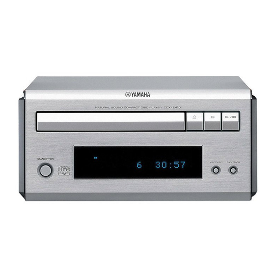
Page 5: Front Panel
CDX-E410 I FRONT PANEL I REAR PANEL B, G models B, G models I SPECIFICATIONS I PLAYBACK SYSTEM • DIMENSIONS CD, CD-R/RW I AUDIO PERFORMANCE Signal to Noise (1 kHz) ................105 dB or more Dynamic Range (1 kHz) ................. 95 dB or more Distortion and Noise (1 kHz) ................ -
Page 6: Internal View
CDX-E410 I INTERNAL VIEW FRONT (2) P.C.B. MAIN (2) P.C.B. MAIN (1) P.C.B. CD Mechanism FRONT (1) P.C.B. I REPAIR NOTES None of the components of the following units can be supplied separately. Each unit must be replaced as a whole in case of a failure. -
Page 7: Disassembly Procedures
CDX-E410 I DISASSEMBLY PROCEDURES See REPLACEMENT PARTS LIST for item numbers. Top Cabinet [28] → Remove 4 screws. [60] (4 on side) Mounting → Remove 4 screws. [51] (4 on rear side) Dismounting → Lift top cover from rear side to remove. -
Page 8: Test Mode
Be sure to prepare, receiver (RX-E410), system control cable and remote control. Preparation and precautions before starting the operation Connect the “TO RX-E410” terminal of the CDX-E410 to the “TO CDX-E410” terminal of the RX-E410 with the system control cable. -
Page 9: Ic Data
CDX-E410 I IC DATA IC21 : TC94A54 (MAIN P.C.B) Pin No. Pin name Description Remark RFZI Input pin for the RF ripple zero-cross signal. To be connected to the RFRP via * No replacement part available. 3AI/F 0.033 uF. AVSS3 –... - Page 10 CDX-E410 Pin No. Pin name Pin name Function Remark Pin No. Pin name Description Remark VDDM – 1.5V supply voltage pin dedicated to the DSP/1Mbit SRAM – LPFN Pin for receiving an inverted output of the PLL-circuit low-pass The resistance side is connected.
- Page 11 CDX-E410 IC22 : TA2125 (MAIN P.C.B) Motor driver * No replacement part available. Driver REG OUT N.C. Control STBY STBY Logic lref N.C. N.C. N.C. N.C. VCIN Symbol Function OUT5A Output terminal H-bridge Supply voltage terminal for Logic H-bridge OUT5B...
- Page 12 CDX-E410 IC71 : CS4392 (MAIN P.C.B) * No replacement part available. (SDA/CDIN) (CL/CCLK) (AD0/CS) AMUTEC BMUTEC CMOUT FILT+ MODE SELECT EXTERNAL REFERENCE (CONTROL PORT) MUTE CONTROL VOLUME AOUTA+ CONTROL ∆∑ INTERPOLATION ANALOG FILTER FILTER AOUTA- SERIAL SCLK MIXER PORT LRCK AOUTB- ∆∑...
- Page 13 CDX-E410 Symbol Function Reset (Input) - Powers down device and resets all intemal registers to their default settings. Logic Power (Input) - Positive power for the digital input/output. SDATA Serial Audio Data (Input) - Input for two’s complement serical audio data.
-
Page 14: Block Diagram
CDX-E410 I BLOCK DIAGRAM X501 IC22 IC51 X201 IC21 CD Mechanism BUS_OUT ST+5V BUS_IN Q501 SYSTEM CONTROL FL51 COAXIAL IC75 S508 OPTICAL IC41 IC71 T401 IC73 IC74 IC42 IC43 IC44 IC72 IC45 Q401 • See page 20 → • See page 19 →... -
Page 15: Wiring Diagram
CDX-E410 I WIRING DIAGRAM MAIN (2) P.C.B. AGND MAIN (1) P.C.B. PWR_ON AGND P_MUTE PWR_ON MGND ST+5V FLT_ON FRONT (2) P.C.B. FLT_ON ST+5V MGND PWR_ON P_MUTE AGND CD Mechanism FRONT (1) P.C.B. -
Page 16: Printed Circuit Boards
CDX-E410 I PRINTED CIRCUIT BOARDS FOR INFORMATION ONLY (NO SERVICE PARTS WILL BE AVAILABLE) MAIN (1) P.C.B. MAIN (2) P.C.B. (Top view) (Top view) DIGITAL OUT TO RX-E410 COAXIAL OPTICAL LINE OUT (SYSTEM CONTROL) MAIN (2) (CN43) MAIN (1) (CN42) - Page 17 CDX-E410 MAIN (1) P.C.B. MAIN (2) P.C.B. (Bottom view) (Bottom view)
- Page 18 CDX-E410 FRONT (1) P.C.B. (Top view) MAIN (1) (CN52) FRONT (2) P.C.B. (Top view) AC IN MAIN (1) (CN41)
-
Page 19: Schematic Diagrams
CDX-E410 I SCHEMATIC DIAGRAMS FOR INFORMATION ONLY (NO SERVICE PARTS WILL BE AVAILABLE) MAIN To CD Machanism MAIN (1) MAIN (2) To CD Machanism To CD Machanism OPTICAL COAXIAL SYSTEM CONTROL Page 20 Page 20 to FRONT (1)_CN52 to FRONT (2)_BN41... - Page 20 CDX-E410 FRONT Page 19 to MAIN (1)_CN52 FRONT (1) STANDBY/ON Page 19 to MAIN (1)_CN41 FRONT (2) AC IN...
- Page 21 CDX-E410 MEMO MEMO MEMO MEMO...
-
Page 22: Replacement Parts List
CDX-E410 I REPLACEMENT PARTS LIST 32 (2) 34 (2) 36-1 32 (1) 34 (1) - Page 23 CDX-E410 WARNING G Components having special characteristics are marked s and must be replaced with parts having specifications equal to those originally installed. Ref. No. Part No. Description Remarks Markets AAX79150 FL WINDOW CGU1A390Z AAX79160 FL SHEET CMZ1A114Z AAX79300 KNOB ORNAMENT...
-
Page 24: System Control
CDX-E410 I SYSTEM CONTROL 1. External Bus 1.1. Physical format of external bus It is composed of 2 bus lines. MCR-E410 RX command line RX unit CD unit (RX-E410) (CDX-E410) State info. line 1.2. Format of RX command RX command is the request of RX to CD unit and the operation button code for CD. - Page 25 CDX-E410 Example: Process Eject Initialize Power on Loading Stop Seek Play Pause Play Skip Play Search Play H x 2/3 H x 1/3 Reset start "STANDBY/ON" "EJECT" Load "PLAY" "PAUSE" "PLAY" "SKIP" "SEARCH" "PLAY" Process Play Stop Seek Play Eject...
- Page 26 CDX-E410 2. Command and Operation Key Code The system command and the system remote control code described as follows are transmitted through RX command bus. 2.1 RX request command Name Code Function POWER_ON 78-7E Power on request POWER_OFF 78-7F Standby request...
- Page 27 CDX-E410 3. Command Communication for System Function 3.1 Power on (1) Power on by RX “STANDBY/ON” key operation RX turns on the power by RX “STANDBY/ON” key and at the same time CD also turns on the power if CD state is power on at the last RX power on.
- Page 28 CDX-E410 3.2 Timer function The unit setted in this RX timer function is playbacked at the setting time as the ON-TIME. It functions even when at setted time the system is already in power on state or the unit is already playbacked.
- Page 29 CDX-E410 3.3 Standby (power off) (1) System standby The power supply through AC outlet of RX is shut down in system standby (power off). The microcomputer of the unit connected with AC outlet of RX cannot work after system power off.
- Page 30 CDX-E410 (3) Auto standby (power off) When 30 minutes pass with the following conditions consisted, the system turns off the power (standby) automatically. a. The unit connected with an external bus is in the standby state. b. RX input function is CD.
- Page 31 CDX-E410 3.4 Display control (1) Display dimmer function This is the function to change the brightness of CD’s display by operating RX. RX unit CD unit Display dimmer on operation DIMMER_ON command Display dimmer on Display dimmer on Display dimmer off operation...
- Page 32 CDX-E410...
Need help?
Do you have a question about the CDX-E410 and is the answer not in the manual?
Questions and answers