Air Techniques AS10 Installation And Operation Manual
Airstar series
dental air system
Hide thumbs
Also See for AS10:
- Installation and operation manual (16 pages) ,
- Pre-installation manual (4 pages) ,
- Assembly instructions (4 pages)
Table of Contents
Advertisement
Advertisement
Table of Contents

Subscribe to Our Youtube Channel
Related Manuals for Air Techniques AS10


Summary of Contents for Air Techniques AS10
- Page 1 DENTAL AIR SYSTEM Installation and Operation Manual...
-
Page 3: Table Of Contents
AS10, AS12, AS21, AS22, AS30, AS40, AS50, AS70, & AS100 TABLE OF CONTENTS SECTION PAGE Congratulations . . . . . . . . . . . . . . . . . . . . . . . . . . . . . . . . . . . . . . . . . . . . . . . . . . . . . . . 4 Safety Instructions . -
Page 4: Congratulations
Compact size for space-saving installation Since 1971, when Air Techniques pioneered the manufacture of oil-less air for dentistry, thousands of dentists have depended on their AIRSTAR . Now that your practice has an AIRSTAR , you, too, can depend on the delivery of 100% oil-less, ultra-dry air and efficient, trouble-free operation . -
Page 5: Safety Instructions
AS10, AS12, AS21, AS22, AS30, AS40, AS50, AS70, & AS100 SAFETY INSTRUCTIONS Use of the AIRSTAR not in conformance with the instructions specified in this manual may result in per- manent failure of the unit. To prevent fire or electrical shock, do not expose this appliance WARNING: to rain in or moisture. -
Page 6: Key Parts Identification
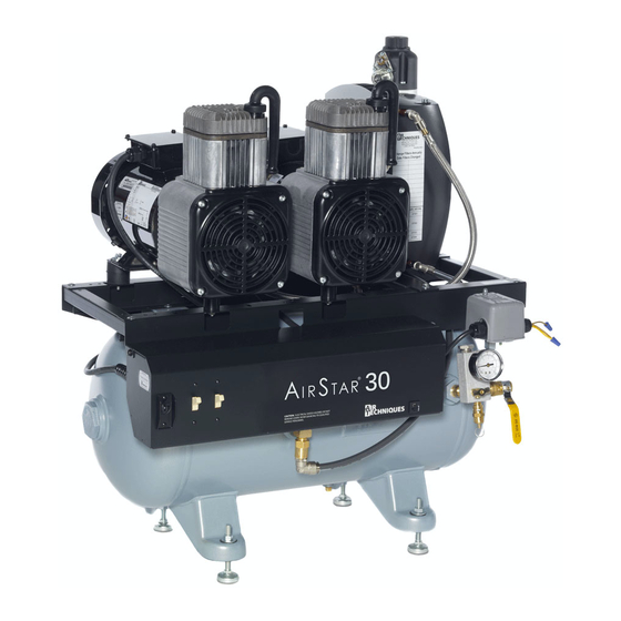
AS10, AS12, AS21, AS22, AS30, AS40, AS50, AS70, & AS100 KEY PARTS IDENTIFICATION Membrane Dryer Cooler Sound Reducing Intake Filters Membrane Dryer Service Timer Control Motor Circuit Breaker Motor Power Membrane Dryer Switches Drain Valve Main Tank Check Valve View B. Right -Side View... -
Page 7: Sizing Guide
AS10, AS12, AS21, AS22, AS30, AS40, AS50, AS70, & AS100 SIZING GUIDE Choosing the correct size AIRSTAR for your practice depends on the number of air users and the anticipated air demand . To assure optimum compressor operation, the air demands should... -
Page 8: Site Requirements
AS10, AS12, AS21, AS22, AS30, AS40, AS50, AS70, & AS100 SITE REQUIREMENTS Service Clearance: Allow 12" on all sides for all models . Ambient Temperature: Must not exceed 105°F Air System Plumbing Connection: 3/8" F .N .P .T . Shut-off valve and a 6 ft . pressure hose (supplied) ... -
Page 9: Overall Site Requirements
AS10, AS12, AS21, AS22, AS30, AS40, AS50, AS70, & AS100 SITE REQUIREMENTS Site Electrical Requirements AirStar Model AS10 AS12 AS21 AS22 AS30 AS40 AS50 AS70 AS100 Requirement Nominal Supply Voltage (VAC, see note) Frequency (Hz) Full Load Amps Minimum Panel Breaker Rating (Amps) Minimum. -
Page 10: Installation Information
AS10, AS12, AS21, AS22, AS30, AS40, AS50, AS70, & AS100 INSTALLATION INFORMATION Each assembly (tank and heads) weighs over 100 pounds and requires two people to lift. AS100 ASSEMBLED at the SITE Installing Left and Right Head Assemblies All AIRSTAR models, except the AS100, are shipped assembled and can be installed upon delivery by following the installation guidelines for plumbing and electrical connections provided by pages 12 &... -
Page 11: Left And Right Head Assembly Motor Connections
AS10, AS12, AS21, AS22, AS30, AS40, AS50, AS70, & AS100 INSTALLATION INFORMATION Make sure all system power is removed prior to working with electrical circuits. Contacting high voltage can cause serious injury or even death. Install strain relief to the motor harness of the left and right head assemblies . Connect ... - Page 12 If voltage is higher than 132V/242V, install a bucking transformer. Note: MINIMUM VOLTAGE: The minimum voltage for an AS10 or AS21 is 108 Volts . The minimum voltage required for an AS12, AS22, AS30, AS40, AS50, AS70 or AS100 is 198 Volts .
-
Page 13: Airstar Electrical Connections
AS10, AS12, AS21, AS22, AS30, AS40, AS50, AS70, & AS100 INSTALLATION INFORMATION 24VDC CONNECTIONS: 24VDC connections are used when installing a 24VDC remote switch . Make the 24VDC connections shown by Figure 3 for the remote switch . When not using the remote switch, insulate the BRN wire and tie the ORG and YEL wires together . - Page 14 Turn on the electricity . Check the incoming line voltage . It should be at least 108 Volts for the AS10 and AS21; and 198 Volts for the AS12, AS22, AS30, AS40, AS50, AS70 and AS100 . This voltage should remain at or above these levels while the AIRSTAR is running .
-
Page 15: Troubleshooting
. 2 . Motor tries to start, cir- a . Voltage too low .If each a . AS10 and AS21 require a minimum of cuit breaker trips off . compressor head runs 108 Volts . AS12, AS22, AS30, AS50,... - Page 16 Test heads by turning ONE on at a time. If the motor fails to start, or the circuit breaker trips, the problem may be in that compressor head. Leave the power switch for the effective head in the OFF position. Call your Authorized Air Techniques dealer for service.
-
Page 17: Maintenance
AS10, AS12, AS21, AS22, AS30, AS40, AS50, AS70, & AS100 MAINTENANCE Like all precision products, your AIRSTAR requires a certain amount of care on a regularly scheduled basis . A well-organized maintenance program aids dependable equipment operation and reduces problems to a minimum . Routine checks help to detect general overall wear, and replacement of parts can often be made before a problem occurs . -
Page 18: Airstar Filter Location
AS10, AS12, AS21, AS22, AS30, AS40, AS50, AS70, & AS100 MAINTENANCE Important: In dusty environments, the Intake Filter, PN 89938, may need to be changed more often than once a year . Always dispose of the removed filter in accordance with local codes . -
Page 19: Service Timer
AS10, AS12, AS21, AS22, AS30, AS40, AS50, AS70, & AS100 MAINTENANCE SERVICE TIMER Timer Display Service Timer Alerts User to Perform Scheduled Maintenance Warranty Indicator The Service Timer is designed to track, in hours, the operating time of the AIRSTAR motors and... -
Page 20: Replacement Parts
AS10, AS12, AS21, AS22, AS30, AS40, AS50, AS70, & AS100 REPLACEMENT PARTS Description Part No. 5 Micron Replacement Filter 87168 Preventive Maintenance Kits AirStar Model Kit Part No. AS10 & AS12 87351 AS21 AS22 AS30 87352 AS40 87355 AS50 87353... -
Page 21: Product Specifications
AS10, AS12, AS21, AS22, AS30, AS40, AS50, AS70, & AS100 PRODUCT SPECIFICATIONS Air Techniques, Inc. Page 21... -
Page 22: Warranty
Any item returned under warranty, will be repaired or replaced at our option at no charge pro- vided that our inspection confirms it to be defective. Air Techniques, Inc. is not liable for indirect or consequential damages or loss of any nature in connection with this equipment . Dealer labor, shipping and handling charges are not covered by this warranty . - Page 23 AS10, AS12, AS21, AS22, AS30, AS40, AS50, AS70, & AS100 NOTES Air Techniques, Inc. Page 23...
- Page 24 For over 50 years, Air Techniques has been a leading innovator and manufacturer of dental products. Our priority is ensuring complete satisfaction by manufacturing reliable products and providing excellent customer and technical support. Whether the need is digital imaging, utility room equipment or merchandise, Air Techniques can provide the solution via our network of authorized professional dealers.
Need help?
Do you have a question about the AS10 and is the answer not in the manual?
Questions and answers