Table of Contents
Advertisement
Advertisement
Table of Contents

Related Manuals for TRU-BOLT 08102017


Summary of Contents for TRU-BOLT 08102017
- Page 1 USER MANUAL - ELECTRONIC DEADBOLT WITH REMOTE 08102017...
-
Page 2: Table Of Contents
Index INSTALLATION INSTRUCTIONS Page 1 Package Contents / Tools Required............Page 2 Prepare Door and Jamb................Page 3 Adjusting Deadbolt Latch Set..............Page 4 Installing Deadbolt Latch Set..............Page 5 Preparing Interior Assembly............... Page 6 Installing Exterior Assembly............... Page 7-8 Installing Interior Assembly................ -
Page 3: Installation Instructions
INSTALLATION INSTRUCTIONS Package Contents Wireless Remote (1 ea.) Entry keys (2 ea.) Deadbolt Latch Set (Adjustable) 2-3/8” (60mm) to 2-3/4” (70mm) Deadbolt Strike Plate Interior Assembly Exterior Assembly Mounting Plate 5/16” (8mm) Screws - 2 ea. 7/8” (22mm) Screws - 2 ea. 3/4”... -
Page 4: Prepare Door And Jamb
PREPARE DOOR AND JAMB NOTE: For installation on doors with pre-drilled holes skip to page 4. 1. TEMPLATE a. Cut out template printed on page 17 & 18 of this Manual (Figure 1a). b. Fold template and place on door 36” (915mm) from the ground as marked (Figure 1b). -
Page 5: Adjusting Deadbolt Latch Set
ADJUSTING DEADBOLT LATCH SET NOTE: Deadbolt Latch Set is shipped with the backset set at 2-3/8” (60mm) Measure the backset (backset is distance between edge of the door and the center of Lock). 1. TO CONVERT FROM 2-3/8” (60mm) BACKSET TO 2-3/4” (70mm) BACKSET a. -
Page 6: Installing Deadbolt Latch Set
INSTALLING DEADBOLT LATCH SET 3. INSTALLING THE DEADBOLT LATCH SET (need Phillips head screwdriver) a. Insert Deadbolt Latch Set into door edge hole with the word “UP” and the arrow on the extension plate facing UP. Cross shaped spindle connector will be at the bottom of the Deadbolt Latch Set (Figure 3a). -
Page 7: Preparing Interior Assembly
PREPARING THE INTERIOR ASSEMBLY 5. UNPACK THE INTERIOR ASSEMBLY a. Remove the battery cover by sliding the cover upward. b. Locate the screw holding the Mounting Plate to the Interior Assembly. Remove the screw to release the Mounting Plate from the Interior Assembly. 6. -
Page 8: Installing Exterior Assembly
INSTALLING EXTERIOR ASSEMBLY 8. INSTALLING THE EXTERIOR ASSEMBLY Work with the Door Open for easy access. a. Unpack the Exterior Assembly. Use care to not scratch the green circuit board during handling and installation. b. Check that the Rubber Gasket is properly seated on the Exterior Assembly (Figure 8a). -
Page 9: Installing Interior Assembly
INSTALLING INTERIOR ASSEMBLY 11. ATTACH THE CONTROL WIRE TO THE INTERIOR ASSEMBLY a. Use care to attach the Control Wire male plug to the Interior Assembly female socket connector. b. Carefully insert the male plug, smooth side up, into the female socket on the interior assembly. -
Page 10: Installing Interior Assembly
Insert 4 AA high quality Alkaline batteries into the Battery Compartment in the direction noted +/- on the Compartment. The Lock will beep 2 times, the keypad will illuminate blue, and the Tru-Bolt button will flash green twice to signify that it has received power (Figure 13a). -
Page 11: Operation Instructions
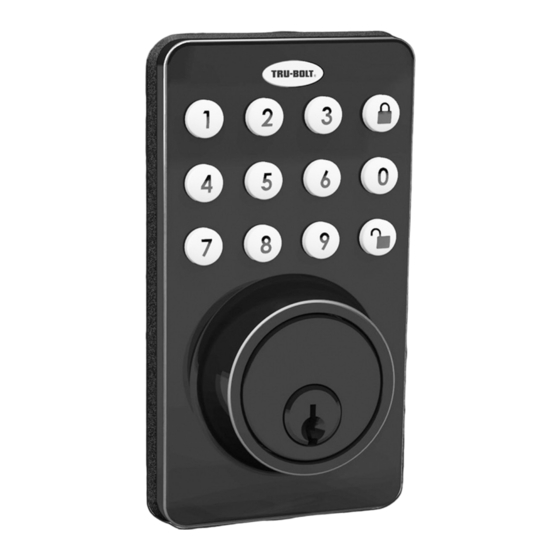
OPERATION INSTRUCTIONS Exterior Assembly Overview Light indicator Green Light Indicator • Indicates Successful Programming Step • Indicates Unlocking is Successful Red Light Indicator • Indicates Failed Programming Step or Installation • Indicates Locking is Successful Lock button Lock - Used to lock door Unlock button Unlock - Used to unlock door / Programming Programming - Used in programming steps... -
Page 12: Adding User Codes
Locking and Unlocking TO LOCK THE LOCK Using Keypad: Press and then hear 2 beeps and lights red. TO UNLOCK THE LOCK Using Keypad: Enter a valid User Code (default code is 1234) and press and hear 1 beep and lights green. Changing Programming Code CHANGE CURRENT OR PRESET PROGRAMING CODE Factory default Programming Code... -
Page 13: Temporarily Disable Auto Lock
Deleting User Codes DELETE ONE EXISTING OR PRESET USER CODE The unit comes with a factory User ID = 01 for User Code = 1234. IMPORTANT: To delete 1 User Code , the lock must have more than 1 User Code in its database. -
Page 14: Remote Control Set-Up And Operation
Remote Control Set-Up and Operation ADD ONE REMOTE CONTROL (You can add up to 20 remotes, ID from 01-20) Press any Existing (01-20) re-enter button on the remote Hear 1 beep and Light Indicator illuminates green. Note: This is the only step you need to use the remote for programming. DELETE ONE EXISTING REMOTE CONTROL Existing (01-20) -
Page 15: Vacation Mode / Sound On And Off / Secure Lock-Out Period
Vacation Mode With Vacation Mode enabled, the system enters into low-power comsumption mode. During this mode, all buttons and functions including the remote control will be invalid until they are re-enabled (see steps below). ENABLE: Hear 1 beep and Light Indicator illuminates green then lock door DISABLE: To disable the Vacation Mode, you must press and hold for more than 3 seconds,... -
Page 16: Consumer Friendly Message Guide
Restore Factory Settings To reset the lock to the original factory settings including the Programming Code and all User Codes remove one battery for 10 seconds. Reinsert the battery and wait for a long and short beep. Press 3 times within 3 seconds. The lock will beep and the light indicator will turn green. -
Page 17: Installation Trouble Shooting
INSTALLATION TROUBLE SHOOTING Issue Solution Latch Working Direction switch is set to incorrect setting. Backwards- Remove the Interior Assembly and move the switch to the opposite Lock unlocks when direction. lock button is pushed • Check that your switch is set in the correct position Left or Right or locks when unlock Handed door. -
Page 18: Consumer Assistance
CONSUMER ASSISTANCE EMAIL: LHICustomerService@lewishymaninc.com WEBSITE: www.truboltlocks.info ADDRESS: Consumer Assistance Dept. Lewis Hyman, Inc., 860 East Sandhill Avenue Carson, CA 90746 USA TELEPHONE: US/Canada 800-860-1677 Ext. 1801(Toll Free) CALL CENTER HOURS: US/Canada 7am – 5pm (Pacific**) Mon – Fri (Subject to change) CALL BACK HOURS: Other Countries 7am –... - Page 19 Page 17...
-
Page 20: Template
Back of Template Page 18... -
Page 21: Programming Record
PROGRAMMING RECORD My Codes: Date Created Programming Code (6 digits) User Code 01 (4-8 digits) User Code 02 (4-8 digits) User Code 03 (4-8 digits) User Code 04 (4-8 digits) User Code 05 (4-8 digits) User Code 06 (4-8 digits) User Code 07 (4-8 digits) User Code 08... -
Page 22: Programming Record
PROGRAMMING RECORD My Codes: Date Created User Code 26 (4-8 digits) User Code 27 (4-8 digits) User Code 28 (4-8 digits) User Code 29 (4-8 digits) User Code 30 (4-8 digits) User Code 31 (4-8 digits) User Code 32 (4-8 digits) User Code 33 (4-8 digits) User Code 34... -
Page 23: Limited Warranty
In no event shall Tru-Bolt® be liable for any special, incidental or consequential damages. If this product[s] is...
Need help?
Do you have a question about the 08102017 and is the answer not in the manual?
Questions and answers
what type of battery does the remote use/take
The TRU-BOLT remote with part number 08102017 uses four (4) high quality AA alkaline batteries.
This answer is automatically generated