Advertisement
Table of Contents
Advertisement
Table of Contents

Related Manuals for Grundfos UP15-42F


Summary of Contents for Grundfos UP15-42F
- Page 1 GRUNDFOS INSTRUCTIONS Grundfos Variable Speed Installation and Operation Pumps Incorporating the (VS) Variable Speed Control with Date Code 0838 or higher Shipment Inspection General Electrical Features Operational Settings Limits Pump Quick Installation Reference...
- Page 2 Grundfos Variable Speed Pump It has been carefully inspected and tested before shipment. It should give you long, efficient, trouble- free service. For maximum performance and reliability, please follow the simple instructions in this manual. When installing and using this electrical equipment, basic...
-
Page 3: Shipment Inspection
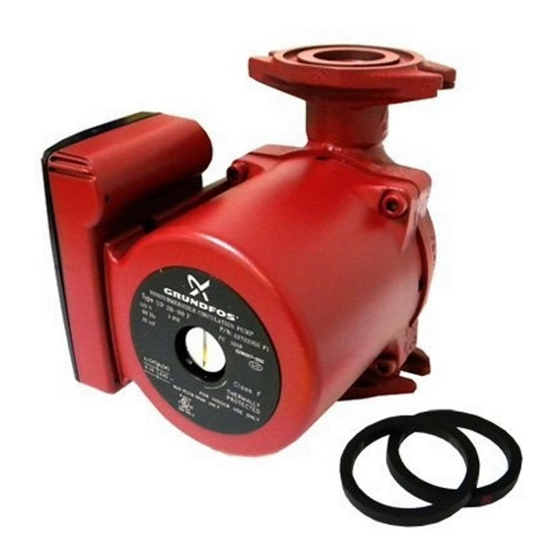
NOT dropped or mishan- dled; dropping will damage the pump. Grundfos Variable Speed Pump Package Includes: • One Grundfos UP15-42 or UP26 Variable Speed pump with integral control. • One 6’ line cord with 115V plug, pre-wired into control box. -
Page 4: Operational Limits
Control Signal Input Range Options: Voltage signal range: 0-10V(DC) or 2-10V(DC) Current signal range: 0-20mA or 4-20mA Grundfos Variable Speed pumps are designed to pump liquids compatible with their cast iron pump housing construction. They are recommended for use in closed hydronic systems. -
Page 5: Pump Installation
Pump Installation Warning: Consult piping manufactures for material selection before installing this pump. Absence of pumping fluid may damage some piping materials. Caution: Thoroughly clean and flush the system prior to pump installation For Indoor Use Only Preferred Pump & Terminal Box Orientation: Page 6 Recommended DO NOT... - Page 6 The pump must be installed with the motor shaft positioned horizontally. Under no circumstances should the pump be installed with the shaft vertical or where the shaft falls below the horizontal plane (Fig. 1). • Ensure that water does not enter the terminal box during the installation process.
- Page 7 Electrical Connections To The Control: CAUTION: The installer should confirm that no current/voltage is present at any of the wires. Note: Control signal wires must be run through and secured by the stain relief on the terminal board. Note: No speed control signal is necessary if speed is to be regulated using the manual % dial.
- Page 8 Settings Settings Settings Setting Dip Switches: Setting Dip Switches Setting Dip Switches � � Figure 5 - Figure 7A - Figure 7A - Dip Switches Dip Switches Dip Switches Dip switch settings Dip switch settings Dip Switch Settings: POSITION POSITION DEFAULT DEFAULT SWITCH...
- Page 9 Multi Function Dial On Terminal Box Multi Function Dial On Terminal Box Multi Function Dial On Terminal Box: Offset Dial (When dip switch D is on) Offset Dial (When dip switch D is ON) Offset Dial (When dip switch D is on) The Offset dial allows the user to fine tune the input The Offset dial allows the user to fine tune the input The Offset dial allows the user to fine tune the input...
-
Page 10: Quick Reference
Quick Reference Voltage Speed Control Signal Circuit Rating: Terminals : Com(-) & Os/V 0-10VDC 5mA Max Settings Current Speed Control Signal Circuit Rating: Terminals : Com(-) & Ret/I Settings Setting Dip Switches 0-20mA DC 5VDC Max Setting Dip Switches � Figure 7A - Dip Switches �... - Page 11 Grundfos Variable Speed Control Board Made in Canada Power: 120 ±10% 50/60 Hz 240 VA Demand: 20-30 V (ac) 0.1 VA A B C D Var. Speed: 120 V (ac) 1.8 A 1/12 hp Relay: 30 V (ac), 2.5 A pilot duty 100µ...
-
Page 12: Limited Warranty
GRUNDFOS are subject to the warranty provided by the manufacturer of said products and not by GRUNDFOS' warranty. GRUNDFOS will not be liable for damage or wear to products caused by abnormal operating conditions, accident, abuse, misuse, unauthorized alteration or repair, or if the product was not installed in accordance with GRUNDFOS' printed installation and operation instructions.
Need help?
Do you have a question about the UP15-42F and is the answer not in the manual?
Questions and answers