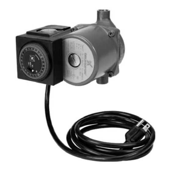
Grundfos UP 15 series Installation & Operating Instructions
Maintenance-free circulators with line
cord and optional timer control
Hide thumbs
Also See for UP 15 series:
- Instructions manual (24 pages) ,
- Installation & operating instruction (8 pages) ,
- Replacement instructions (2 pages)
Advertisement
Quick Links
1. Shipment Inspection
Examine the components carefully to make sure no
damage has occurred to the pump during shipment. Care
should be taken to ensure the pump is NOT dropped or
mishandled; dropping will damage the pump.
2. Pre-Installation Checklist
Before beginning installation procedures, the
following checks should be made. They are all
important for proper installation of the circulator
pump.
1. Uses:
Model UP 15 series pumps are designed to circulate
water from 50°F to 230°F up to a maximum pressure of
145 psi. If required, a 50% by volume solution of ethylene
or propylene glycol and water can be used, however, a
psi decrease in pump performance may result due to an
increase in the viscosity of the solution. Check with
manufacturer for information regarding suitability of
pumping other fluids.
System Applications: UP15 series pumps with
stainless steel or bronze volutes can be used in both
open and closed systems.
2. Maximum Water Temperature:
UP15 pump with line cord only. The maximum allowable
water temperature is determined by the ambient or
surrounding air temperature as shown in Table 2A.
Table 2A – Maximum Water Temperature
Ambient (°F)
95
130
140
160
Water (°F)
230
220
210
190
Although the pump is designed to operate at maximum
water temperature of 230°F, it is recommended to
keep the operating temperature as low as possible (i.e.
below 140°F to avoid precipitation of calcium).
3. Inlet Pressure Requirements
The amount of pressure required at the inlet of the pump
is a function of the temperature of the water as shown in
Table 2B.
Table 2B – Inlet Pressure Requirements
Water (°F)
190
Required Inlet Pressure (ft.)
(psi)
In a pressurized system, the required inlet pressure is the
minimum allowable system pressure.
In an open system, the required inlet pressure is the
minimum distance the pump must be located below the
lowest possible water level of the water source (tank,
pool, etc.).
3. Pump Installation
Position of terminal box:
Proper installation of the pump will have the terminal box
located to one side of the pump or the other, with the
conduit entry down. See Figure 3A.
Figure 3A
Recommended Terminal Box Orientation
If the terminal box position needs to be changed, it is best
to do so before installation. However, if the pump is already
installed, ensure that the line cord is unplugged and close
the isolation valves before removing the Allen screws.
To change terminal box position:
1. Remove the four (4) Allen screws from the pump
housing and stator (4 or 5mm wrench) while supporting
the stator (motor).
2. Carefully separate the stator from the pump housing
and rotate it to the correct terminal box orientation and
175
reseat it.
175
3. Replace the Allen screws and tighten diagonally and
evenly (7 ft.-lb. torque).
4. Check that the motor shaft turns freely. Remove the
large screw in the middle of the nameplate, insert a
small flat blade screwdriver into the end of the shaft,
and turn gently (see fig. 7a).
If the shaft does not turn easily, repeat the disassembly/
reassembly process.
Page 1
NOTE: UPS15-42 does not require manual turning of shaft.
165
140
5
4.5
3
Pump Mounting: For Indoor Use
2.2
1.9
1.3
Arrows on the side or bottom of the pump housing indicate
direction of flow through the pump. GRUNDFOS
circulators can be installed in both vertical and horizontal
lines. The pump must be installed with the motor shaft
positioned horizontally. Under no circumstances should
the pump be installed with the shaft vertical or where the
shaft falls below the horizontal plane. See Figure 3B.
Figure 3B
Acceptable
It is recommend that isolation valves be installed on each
side of the pump. If possible, do not install elbows, branch
tees, and similar fittings just before or after the pump.
Provide support to the pump or adjacent plumbing to
reduce thermal and mechanical stress on the pump.
Installation Requirements
1. Thoroughly clean and flush the system prior to pump
installation.
2. Do not install the pump at the lowest point of the system
where dirt and sediment naturally collect.
3. Install an air vent at the high point(s) of the system to
remove accumulated air.
4. Ensure that water does not enter the terminal box
during the installation process.
5. (Open System) Install the pump in the supply line; the
suction side of the pump should be flooded with water.
Ensure that the static head requirement from Table 2B
is achieved.
6. (Closed System) Install a safety relief valve to protect
against temperature and pressure build-up.
7. If there are excessive suspended particles in the water,
it is recommended that a strainer and/or filter be
installed and cleaned regularly.
8. DO NOT START THE PUMP UNTIL THE SYSTEM
HAS BEEN FILLED AND CHECKED FOR LEAKS OR
OTHER POSSIBLE COMPONENT FAILURES.
Page 2
4. Electrical
Warning - Risk of electrical shock - This pump is supplied
with a grounding conductor. To reduce the risk of electric
shock, be certain that it is connected only to a properly
grounded grounding type receptacle.
The safe operation of this pump requires that it be grounded
in accordance with the National Electrical Code and local
governing codes and regulations.
Electrical Requirements
The operating voltage and other electrical data are marked
on the motor label. Make sure that the motor is suitable for
the electrical supply on which it will be used.
Electrical Connection
Insert the 115V plug on the line cord from the pump into a
properly grounded 115V outlet as shown in Figure 4a.
Unacceptable
5. Timer Technical Data
TIMER CONTROL
Supply Voltage: 115-120 VAC, 60 hertz
Contact Rating: 16 amps
Ambient Temperature: -4°F to 175°F
Shortest Switching Interval: 15 minute increment
Switch Modes:
Protection:
Note: UP15 pump with timer control maximum water tem-
perature: 150°F
6. Timer Technical Application
The Grundfos timer control is designed only for use with
specified Grundfos Series UP circulators installed in in-
door hot water service systems.
The timer control is designed to turn the circulator on and
off at preset times, allowing the user to select operation of
the circulator during high use periods of the day.
Page 3
SAFE WARNING
"Timer", "ON" Override,
"OFF" Override
Clear plastic cover for dust and
moisture protection of the clock face.
Page 4
Advertisement

Subscribe to Our Youtube Channel
Related Manuals for Grundfos UP 15 series


Summary of Contents for Grundfos UP 15 series
- Page 1 Acceptable Unacceptable conduit entry down. See Figure 3A. Model UP 15 series pumps are designed to circulate It is recommend that isolation valves be installed on each water from 50°F to 230°F up to a maximum pressure of Figure 3A 5.
- Page 2 L th L th Line (GRUNDFOS) are warranted to the original user only to be free of defects either the programming ring or the timer switch. and Starting the Pump in material and workmanship for a period of 18 months from date of...
Need help?
Do you have a question about the UP 15 series and is the answer not in the manual?
Questions and answers