COBHAM SAILOR 6280 Installation Manual
Ais system
Hide thumbs
Also See for SAILOR 6280:
- User manual (76 pages) ,
- User manual (90 pages) ,
- User manual (90 pages)
Table of Contents
Advertisement
Quick Links
Download this manual
See also:
User Manual
Advertisement
Table of Contents

Related Manuals for COBHAM SAILOR 6280


Summary of Contents for COBHAM SAILOR 6280
- Page 1 SAILOR 6280/6281 AIS System Installation manual...
- Page 3 SAILOR 6280/6281 AIS System Installation manual Document number: 98-137573-A Release date: June 28, 2013...
- Page 4 Thrane & Thrane is not responsible for the content or accuracy of any translations or reproductions, in whole or in part, of this manual from any other source. Thrane & Thrane A/S trading as Cobham SATCOM. Copyright © 2013 Thrane & Thrane A/S. All rights reserved.
-
Page 5: Compass Safe Distance
Failure to comply with these precautions or with specific warnings elsewhere in this manual violates safety standards of design, manufacture and intended use of the equipment. Cobham SATCOM assumes no liability for the customer's failure to comply with these requirements. - Page 6 Preface Approvals The SAILOR 6282 AIS Transponder fulfills the requirements of the Marine Equipment Directive 96/98/EC with 8th amend 2012/32/EU and is intended for use in maritime environment. The SAILOR 6282 AIS Transponder is approved to MED 2011/75/EU and fulfills the requirements in the standards: IEC 61993-2 (2012), IEC 60945 ed.4 (2002), ITU-R M.1371-4, IEC 61162-1 (2010), IEC61162-2 (1999), IEC61162-450 (2011).
- Page 7 Training information The SAILOR 6282 AIS Transponder is designed for occupational use only and is also classified as such. It must only be used in the course of employment by individuals aware of the hazards as well as the way to minimize those hazards.
- Page 8 • Never touch the antenna when transmitting • Use only authorized SAILOR accessories. 3. If the antenna has to be placed in public areas or near people with no awareness of the radio transmission, the antenna must be placed at a distance not less than 6 ft. (1.8 m) from possible human access.
-
Page 9: Table Of Contents
Cable requirements ......................3-3 3.2.3 VHF RX/TX antenna ......................3-4 3.2.4 SAILOR 6285 GPS Antenna - Active ................3-5 Physical installation of the SAILOR 6280 AIS System .......3-6 3.3.1 SAILOR 6280 AIS System - wiring ................3-10 3.3.2 Cable specifications ......................3-11 Physical installation of the SAILOR 6281 AIS System ....3-12 3.4.1... - Page 10 Table of contents Physical installation of the SAILOR 6004 Control panel ....3-17 Chapter 4 Interface description Power ............................4-1 4.1.1 Connecting DC power .......................4-2 Sensor input .........................4-3 4.2.1 Electrical characteristics ....................4-3 4.2.2 Sensor configuration ......................4-4 4.2.3 Position (GNS, RMC, DTM, GGA) .................4-4 4.2.4 Heading (HDT) ........................4-5 4.2.5...
- Page 11 Table of contents 5.3.9 Connecting a chart plotter ..................5-19 Verification .........................5-20 5.4.1 NMEA Trace tool ......................5-20 Chapter 6 Service & maintenance Contact for support ......................6-1 Maintenance .........................6-1 6.2.1 Preventive maintenance ....................6-1 6.2.2 Error messages ........................6-1 6.2.3 Software update using the TMA (ThraneLINK Management Application) 6-2 Disassembling ........................6-3 6.3.1 Removing the SAILOR 6282 AIS Transponder from the wall tray ....6-3...
- Page 12 Table of contents B.2.9 EPV - Command or report equipment property value (input / response output) B.2.10 GBS - GNSS satellite fault detection (input) ............B-6 B.2.11 GGA - Global positioning system (GPS) fix data (input) ........B-7 B.2.12 GNS - Fix data (input) ......................B-7 B.2.13 HBT - Heartbeat supervision sentence (input) ............B-8 B.2.14 HDT - Heading true (input) .....................B-8 B.2.15 LR1 - AIS long-range reply sentence 1 (output) ...........B-8...
-
Page 13: About This Manual
About this manual Intended readers This is an installation manual for the SAILOR 6280/6281 AIS System. It is intended for installers of the system and service personnel. Personnel installing or servicing the system must be properly trained by Cobham SATCOM. It is important that you observe all safety requirements listed in the beginning of this manual, and install the system according to the guidelines in this manual. -
Page 14: Precautions
The warnings and cautions that follow apply to all parts of this manual. CAUTION! Do not use materials that are not equivalent to materials specified by Cobham SATCOM. Materials that are not equivalent can cause damage to the equipment. CAUTION! The system contains items that are electrostatic discharge sensitive. -
Page 15: Introduction To Ais
Chapter 2 Introduction This chapter has the following sections: • Introduction to AIS • SAILOR 6280/6281 AIS System • System components • Part numbers and options Introduction to AIS 2.1.1 Overview AIS (Automatic Identification System) is a communication system for the exchange of navigation data. -
Page 16: Ais Applications And Purpose
Introduction to AIS 2.1.2 AIS applications and purpose The principal applications of AIS are: • Information exchange between vessels within VHF range of each other, increasing situation awareness • Information exchange between a vessel and a shore station, such as a Vessel Traffic Service (VTS), to improve traffic management in congested waterways •... -
Page 17: Ais Classes
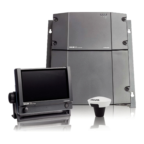
International Maritime organization (IMO). The SAILOR 6282 AIS Transponder is a Class A AIS. SAILOR 6280/6281 AIS System The SAILOR 6280 AIS System consists of the following units: 1. SAILOR 6282 AIS Transponder 2. SAILOR 6285 GPS Antenna - Active 3. -
Page 18: Features
SAILOR 6280/6281 AIS System The SAILOR 6004 Control Panel is connected to the SAILOR 6282 AIS Transponder through a LAN connection (LWE/IEC 61162-450), here after called LWE. The SAILOR 6281 AIS Basic System is operated using the touch display of the SAILOR 6004 Control Panel. -
Page 19: System Components
System components System components 2.3.1 SAILOR 6282 AIS Transponder The SAILOR 6282 AIS Transponder is a Class A AIS. It has connectors for GPS and VHF antenna, a ground stud, connector for DC power (12–24 VDC), multi connector for interfaces and 2 LAN connectors. The SAILOR 6282 AIS Transponder is always on, provided there is DC power. -
Page 20: Sailor 6004 Control Panel
System components 2.3.3 SAILOR 6004 Control panel The SAILOR 6004 Control panel is the user interface for the SAILOR 6282 AIS Transponder. Through the touch panel you access all settings that can be changed by the user. Alarms and notifications are shown in the display. The SAILOR 6004 Control panel has a buzzer for alarm tones. -
Page 21: Part Numbers And Options
SAILOR 6004 Control Panel 406285A SAILOR 6285 GPS Antenna - Active 406283A SAILOR 6283 AIS Connection Box and Wall Tray Table 2-1: Part numbers for the SAILOR 6280/6281 AIS System 2.4.2 Accessories The following accessories are included in the delivery: Part number... - Page 22 Part numbers and options Chapter 2: Introduction 98-137573-A...
-
Page 23: Installation
• SAILOR 6282 AIS Transponder • SAILOR 6285 GPS Antenna - Active • GPS antenna bracket • User manual SAILOR 6282 AIS Transponder & SAILOR 6280/6281 AIS System • Installation guide SAILOR 6282 AIS Transponder • Installation guide SAILOR 6285 GPS Antenna - Active •... -
Page 24: Vhf And Gps Antenna Installation
VHF and GPS antenna installation WARNING! To avoid electric shock, do not apply power to the system if there is any sign of shipping damage to any part of the front or rear panel or the outer cover. Read the safety summary at the front of this manual before installing or operating the system. -
Page 25: Cable Requirements
VHF and GPS antenna installation Combined VHF and GPS antenna SAILOR 6004 Control Panel SAILOR 6282 AIS Transponder FUSE VHF/GPS 12-24V DC SUB-D50 12 – 24 VDC Service PC Figure 3-1: Installation of a combined VHF and GPS antenna 3.2.2 Cable requirements Connect the antennas using a low loss type 50 Ohm coaxial cable, e.g. -
Page 26: Vhf Rx/Tx Antenna
VHF and GPS antenna installation 3.2.3 VHF RX/TX antenna In installations with two or more units it is important to ensure the optimum performance of these by carefully selecting the antenna positions for both units. It is recommended to maximize the RF attenuation between the VHF RX/TX antennas in the installation. You can ensure this by not having the RX/TX antennas positioned at the same horizontal level, i.e. -
Page 27: Sailor 6285 Gps Antenna - Active
VHF and GPS antenna installation 3.2.4 SAILOR 6285 GPS Antenna - Active To install the SAILOR 6285 GPS Antenna - Active do as follows: 1. Install the bracket on the pipe. Use silicone glue to lock the bracket to the pipe. 2. -
Page 28: Physical Installation Of The Sailor 6280 Ais System
Physical installation of the SAILOR 6280 AIS System Physical installation of the SAILOR 6280 AIS System The SAILOR 6280 AIS System consists of the following units: 1. SAILOR 6282 AIS Transponder 2. SAILOR 6004 Control Panel 3. SAILOR 6285 GPS Antenna - Active 4. - Page 29 Physical installation of the SAILOR 6280 AIS System Compass safe distance Make sure that the SAILOR 6282 AIS Transponder is far enough from any magnetic compass. See the following table for the safe distance after magnetization between the nearest point of the device and the centre of the compass at which it will produce a deviation of 0.3°.
- Page 30 Physical installation of the SAILOR 6280 AIS System Connector overview – SAILOR 6282 AIS Transponder The following figure shows the connectors of the SAILOR 6282 AIS Transponder. VHF/GPS 12-24V DC FUSE SUB-D50 Figure 3-6: Connectors of the SAILOR 6282 AIS Transponder VHF/GPS Connect the VHF antenna or the combined VHF/GPS antenna to this connector.
- Page 31 Physical installation of the SAILOR 6280 AIS System AIS ON Rx A Rx A Rx A Rx B ON_IN Rx C Rx B Rx B Rx C ON_OUT Rx C Rx A Rx A Rx A Rx A Rx B...
-
Page 32: Sailor 6280 Ais System - Wiring
Physical installation of the SAILOR 6280 AIS System 3.3.1 SAILOR 6280 AIS System - wiring Figure 3-8: SAILOR 6280 AIS System, wiring 3-10 Chapter 3: Installation 98-137573-A... -
Page 33: Cable Specifications
Physical installation of the SAILOR 6280 AIS System 3.3.2 Cable specifications Number Cable for: Specification Length VHF antenna Coaxial RG 214 or similar Max. 45 m Comrod VHF / GPS antenna type AC17M4-AIS, Max. 40 m Combined antennas item number 014822. -
Page 34: Physical Installation Of The Sailor 6281 Ais System
Physical installation of the SAILOR 6281 AIS System Physical installation of the SAILOR 6281 AIS System The SAILOR 6281 AIS System consists of the following units: 1. SAILOR 6282 AIS Transponder 2. SAILOR 6004 Control Panel 3. SAILOR 6285 GPS Antenna - Active You can mount the SAILOR 6282 AIS Transponder on a desktop or on a wall. - Page 35 Physical installation of the SAILOR 6281 AIS System Fasten the SAILOR 6282 AIS Transponder using the delivered screws according to the following measures: 4 x M5 or hole for self-tapping ø4.8mm 12.5 mm 245 mm 12.5 mm 270 mm Figure 3-10: Measures for installing the SAILOR 6282 AIS Transponder Connector overview The following figure shows the connectors of the SAILOR 6282 AIS Transponder.
- Page 36 Physical installation of the SAILOR 6281 AIS System DC Power input 12–24 VDC For more information on DC power input, pin allocation and instructions how to connect DC power see Connecting DC power on page 4-2. SUB-D50 connector and cable For a detailed description of the View on SAILOR 6282 AIS Transponder interfaces see Interface description on...
- Page 37 Physical installation of the SAILOR 6281 AIS System LAN connector and cable The SAILOR 6282 AIS Transponder has two LAN connections used for connection to the display and keyboard of the SAILOR 6004 Control Panel and for ThraneLINK Management Application (Service Tool). The two connectors are identical and of the type RJ45 with 8 leads For GMDSS installations: Only connect units that Important...
-
Page 38: Sailor 6181 Ais Basic System - Wiring
Physical installation of the SAILOR 6281 AIS System 3.4.1 SAILOR 6181 AIS Basic System - wiring Figure 3-12: SAILOR 6281 AIS Basic System, wiring For cable specifications see Cable specifications on page 3-11. 3-16 Chapter 3: Installation 98-137573-A... -
Page 39: Physical Installation Of The Sailor 6004 Control Panel
Physical installation of the SAILOR 6004 Control panel Physical installation of the SAILOR 6004 Control panel For instructions how to install the SAILOR 6004 Control Panel see separate installation manual for the SAILOR 6004 Control panel (part number 98-136644). Connect a LAN connector at the SAILOR 6282 AIS Transponder to a LAN connector at the SAILOR 6004 Control Panel. - Page 40 Physical installation of the SAILOR 6004 Control panel 3-18 Chapter 3: Installation 98-137573-A...
-
Page 41: Interface Description
Chapter 4 Interface description This chapter describes the electrical interfaces of the SAILOR 6282 AIS Transponder in details. It has the following sections: • Power • Sensor input • Presentation Interfaces • Alarm relay • Low power forced control (gas alarm) 1 W •... -
Page 42: Connecting Dc Power
Power 4.1.1 Connecting DC power Connect DC+ (red wire) to DC out + from your DC supply. Connect DC- (black wire) to DC out - from your DC supply. Connect the white wire in the power cable to DC- (black wire) unless you want to use the Remote on/off (ON_IN) function. -
Page 43: Sensor Input
Sensor input Sensor input The SAILOR 6282 AIS Transponder has three sensor inputs (SENSOR 1, SENSOR 2 and SENSOR 3). These can be connected to the ship’s sensors which can provide information about e.g. speed over ground (SOG), course over ground (COG), heading (HDT), rate of turn (ROT) and position. -
Page 44: Sensor Configuration
Sensor input 4.2.2 Sensor configuration All three sensor inputs are IEC61162-1/2 (RS-422) compliant and can be configured individually with different baud rates. From the factory the ports are set up with the default baud rate as stated in the following table: Port ID Default baud rate Function... -
Page 45: Heading (Hdt)
Sensor input 4.2.4 Heading (HDT) The SAILOR 6282 AIS Transponder can process heading information from heading sensors that provide an IEC 61162 output. If THS (True Heading and Status) and HDT are available, THS is preferred. 4.2.5 Rate of Turn (ROT) If a Rate of Turn (ROT) sensor is available and provides an IEC 61162 output, the sensor must be connected to the SAILOR 6282 AIS Transponder. -
Page 46: Presentation Interfaces
Presentation Interfaces Presentation Interfaces 4.3.1 Overview The SAILOR 6282 AIS Transponder has four presentation interfaces (PI1, PI2, PI3 and PI4). A presentation interface is a bidirectional interface used for e.g. an ECDIS, pilot plug, Long Range equipment or similar. The presentation interfaces are connected through the SUB-D 50 pin connector, which is connected to the SAILOR 6283 AIS Connection Box and Wall Tray or the multi-wire cable supplied with the SAILOR 6282 AIS Transponder. -
Page 47: Electrical Characteristics
Presentation Interfaces 4.3.2 Electrical Characteristics The schematics for the presentation interfaces is shown in the following figure. The presentation interfaces support both IEC61162-1 and IEC61162-2, i.e. baud rates from 4800 to 38400, input voltages down to 0.3 VDC and electrical isolation between each sensor input and the internal power supply. -
Page 48: Pilot Plug Connection
Presentation Interfaces 4.3.4 Pilot plug connection The pilot plug provides a connection to the SAILOR 6282 AIS Transponder for pilots using the standard pilot plug connector. This connector is supplied with the SAILOR 6282 AIS Transponder. Mount it in an appropriate position for easy access by the pilot. The connector kit for the pilot plug consists of the following items: Type Manufacturer... -
Page 49: Alarm Relay
Alarm relay Alarm relay The SAILOR 6282 AIS Transponder has an internal alarm relay. Connect the alarm relay to an audible alarm device or the ships alarm system, if available. The ship’s alarm system is connected to the alarm relay through the SUB-D 50 pin connector, which is connected to the SAILOR 6283 AIS Connection Box and Wall Tray or the multi-wire cable included. -
Page 50: Blue Sign Input
Blue sign input Blue sign input Blue sign is used on vessels that are subject to the Inland Waterway specifications where the Blue sign is used as a special manoeuvre indicator. The SAILOR 6282 AIS Transponder supports a direct connection to the Blue sign switch and is able to detect three logical states: •... -
Page 51: Configuration Of Blue Sign Input
Ethernet interfaces The Blue sign switch has two states: Set or Not Set. Each state activates one or the other optocoupler. If the switch or wire becomes open circuit both optocouplers are activated. If Blue sign is not used (12–24 VDC not connected or a broken wire) both optocouplers are deactivated. - Page 52 Ethernet interfaces Unit Default LWE ID SAILOR 6282 AIS Transponder (default) AI0001 SAILOR 6004 Control Panel (must be set) AI0002 Table 4-7: LWE ID for SAILOR 6282 AIS Transponder SAILOR 6004 Control Panel Both IDs are visible in the display of the SAILOR 6004 Control Panel in the AIS app in section Settings >...
-
Page 53: Configuration
Chapter 5 Configuration This chapter has the following sections: • Start up • AIS app installation and system settings • Service Interface Start up To Power on and off 5.1.1 As soon as DC power is provided the SAILOR 6282 AIS Transponder is on. To switch on the SAILOR 6004 Control Panel push the power button. -
Page 54: Ais App Installation And System Settings
AIS app installation and system settings AIS app installation and system settings 5.2.1 System app Having switched on the SAILOR 6004 Control Panel, an icon named System is always displayed, plus the icon(s) of the applications that are installed. Under System you can set up and manage the SAILOR 6004 Control Panel. - Page 55 AIS app installation and system settings To change a setting you must enter the password for user level and tap OK. Figure 5-2: System - Settings, Display Applications Tap Applications to install or uninstall applications. This section has two tabs: Available, showing the apps that are available to the SAILOR 6004 Control Panel on the current network, and Installed, showing which apps are already installed.
-
Page 56: Ais App - Daily Use
Supported keys on page C-1. Service Interface Before the SAILOR 6280/6281 AIS System can be used on board you must set up several parameters in the SAILOR 6282 AIS Transponder. To do this, use the Service Interface. - Page 57 Service Interface Using a PC with Thrane Management Application (TMA) To access the built-in web interface, also called the Service Interface, via the TMA do as follows: 1. Switch on the SAILOR 6004 Control Panel and make sure that DC power is provided for the SAILOR 6282 AIS Transponder.
- Page 58 Service Interface 5. Open an Internet browser (Firefox or Chrome recommended) and enter the IP address of the SAILOR 6282 AIS Transponder (Remote IP address), e.g.: http://10.10.8.45/index.html Figure 5-5: Start screen of the Service Interface in an Internet browser The start screen of the Service Interface is displayed. The SAILOR 6282 AIS Transponder (also called AIS Important Transceiver) is locked for normal use for as long as...
- Page 59 Service Interface Figure 5-7: Service Interface – general settings 98-137573-A Chapter 5: Configuration...
-
Page 60: General Settings
Service Interface 5.3.2 General settings Enter the general settings and click Submit to store the settings in the SAILOR 6282 AIS Transponder. Figure 5-8: Service Interface: General settings Callsign Enter the callsign of the vessel. MMSI Enter the vessel’s MMSI number. Ship name Enter the vessel’s name. - Page 61 Service Interface Ship type Select a ship type from the drop-down list or select Numeric entry to enter directly the 2- digit value for the ship type. Ship types Ship types (Continued) Not available Pleasure Craft Future ship types Vessel - 38 Vessel - 39 Pilot Vessel Passenger Ships...
-
Page 62: Long Range
Service Interface Message 5 will indicate "1" (unavailable) if no MKD connection (no HBT - heart beat) or if an established connection is lost (HBT time-out). Message 5 will indicate "0" (available) if MKD connection (HBT - heart beat) is detected. Type of electronic position fixing device Select the desired electronic position fixing device. -
Page 63: Password Settings
Service Interface 5.3.4 Password settings Here you can change the password for user and administrator level. The password for user level is used when unlocking a setting using the SAILOR 6004 Control Panel. The password for administrator level is used when accessing the SAILOR 6282 AIS Transponder Service Interface through the Figure 5-10: Service Interface: Password settings... -
Page 64: Interface Settings
Service Interface 5.3.5 Interface settings The purpose of the UART interface settings is to control the information coming into the 4 PI ports and the 3 sensor input ports and to configure for the desired purposes. PI Settings (Presentation Interface bi-directional ports) The PI ports can be configured to encode and decode different categories/purposes: •... - Page 65 Service Interface Item Description Name You can name PI1 through PI4 according to your system requirements. Baud Use the drop-down list to change the baud rate, if needed (default: 38400 baud). Talker ID Filter Enter NMEA talker ID. Replace * from left to right. Example: AI ZZ BI0000 CC9999 GH ZI VA ST ** Talker ID filters are used to ensure that the SAILOR 6282 AIS TransponderAIS does not get the same sentence type from more than one physical sensor.
- Page 66 Service Interface The sensor inputs can in principle also be configured to decode the same sentence Note categories as the PI ports, but as the sensor ports are pure input ports query sentences will not be acknowledged correctly. Figure 5-12: Service Interface: Interface settings – Sensor Settings Item Description Name...
- Page 67 Service Interface Ethernet Settings Figure 5-13: Service Interface: Interface settings – Ethernet Settings If needed you can set the SAILOR 6282 AIS Transponder to have a static IP address. Item Description DHCP/Auto IP (recommended and default) or Static IP Static settings If you need a static IP you must enter the following: –...
- Page 68 Service Interface LWE Settings Set the LWE Settings as shown in the figure below to achieve connection to the SAILOR 6004 Control panel. Figure 5-14: Service Interface: Interface settings – LWE Settings (default) Item Description Name You can name Multicast groups1 through 4 according to your system requirements.
-
Page 69: Read Logs
Service Interface 5.3.6 Read logs Figure 5-15: Service Interface: Read Logs Log type Description System Malfunction Log This log shows: • offTime – start time of event • onTime – stop time of event • reason – Reason codes are explained on the screen •... -
Page 70: System Control
Service Interface 5.3.7 System control Figure 5-16: Service Interface: System control System Control Description Click Factory Reset to reset the SAILOR 6282 AIS Transponder to default Factory Reset values. All user settings are deleted. Click Backup to make a clone of the current setup of the SAILOR 6282 AIS Cloning Transponder. -
Page 71: Connecting A Chart Plotter
Service Interface 5.3.9 Connecting a chart plotter To set up the chart plotter to work together with the SAILOR 6282 AIS Transponder do as follows: 1. Connect a chart plotter to a free PI interface. 2. Login to the Service Interface. 3. -
Page 72: Verification
5.4.1 NMEA Trace tool After installation of all devices to the SAILOR 6280/6281 AIS System it can be useful to start the NMEA Trace tool to see current system information whether the connected device on a selected port receives and sends correct NMEA information. The tool runs independently from the Service Interface and you can access the SAILOR 6282 AIS Transponder as in normal operation. -
Page 73: Chapter 6 Service & Maintenance
Service & maintenance Contact for support Contact your authorized dealer for technical service and support of the SAILOR 6280/6281 AIS System. Before contacting your authorized dealer you can go through the troubleshooting guide to solve some of the most common operational problems. -
Page 74: Software Update Using The Tma (Thranelink Management Application)
Software update using the TMA (ThraneLINK Management Application) 1. Download the TMA from the Cobham eSupport web site (Self-Service Center, SSC. You find the SSC in the Service and Support section, 24-7 Service). Make sure to use version 1.03 or higher. -
Page 75: Disassembling
Disassembling Disassembling 6.3.1 Removing the SAILOR 6282 AIS Transponder from the wall tray 1. Remove the cover of the SAILOR 6283 AIS Connection Box and Wall Tray by loosening the two screws marked 1. Figure 6-3: Removing the cover of the SAILOR 6283 AIS Connection Box and Wall Tray 2. -
Page 76: Alarms And Notifications
Alarms and notifications Alarms and notifications 6.4.1 Overview If an alarm is reported from the SAILOR 6282 AIS Transponder a flashing red triangle appears in the bottom bar of the SAILOR 6004 Control Panel display: • Flashing, bright red triangle: Unacknowledged alarm(s). •... -
Page 77: List Of Alarms
Alarms and notifications 6.4.2 List of alarms Alarm Consequence Reason Remedy Connection AIS list is empty, Someone has logged into After logout from lost the padlock for the TT-6282A AIS Service the TT-6282A AIS password Interface. Service Interface protection resumes normal TRX has no power cannot be operation. - Page 78 Alarms and notifications Alarm Consequence Reason Remedy Rx channel The SAILOR If continuous monitoring Check the VHF AIS 2 6282 AIS of the receiver channel 2 antenna, plugs, and malfunction Transponder shows inconsistency, this cable to the AIS (ID 004) stops alarm is activated.
- Page 79 Alarms and notifications Alarm Consequence Reason Remedy The SAILOR This alarm is activated by Check the power Connection 6282 AIS the system, if the AIS supplies, cabling, lost Transponder Transponder does not Ethernet (ID 008) continues receive heartbeat connection operation with messages from at least between the AIS DTE set to 1, the...
- Page 80 Alarms and notifications Alarm Consequence Reason Remedy Active AIS- The SAILOR This alarm is activated SART 6282 AIS when the SAILOR 6282 (ID 014) Transponder AIS Transponder receives continues a position report from an operation. AIS search and rescue transponder (SART). The AIS SART indicates the position of persons in distress.
- Page 81 Alarms and notifications Alarm Consequence Reason Remedy No valid The SAILOR This alarm is activated Check the NMEA 6282 AIS when none of the sensor connection information Transponder inputs reports a valid between speed (ID 029) continues speed over ground (SOG). measuring device operation using and AIS...
- Page 82 Alarms and notifications Alarm Consequence Reason Remedy No valid The SAILOR This alarm is issued if the Check the NMEA 6282 AIS rate of turn (ROT) cannot connection information Transponder be determined from between ROT (ID 035) continues sensor data or internal sensor and AIS operation using calculations.
-
Page 83: Troubleshooting Guide
Troubleshooting guide Troubleshooting guide Problem Symptom Remedy The SAILOR Green LED on If the power cable is connected directly to 6282 AIS SAILOR 6282 the SAILOR 6282 AIS Transponder then Transponder check that the white wire in the power will not turn Transponder cable is connected to the black wire (-DC). -
Page 84: Recovering Communication With The Sailor 6004 Control Panel
Troubleshooting guide Problem Symptom Remedy If the SAILOR 6004 Control Panel cannot SAILOR be switched off normally (e.g. due to a 6004 fault): Push and hold for 12 seconds. Control Panel cannot be switched off. Check that you enter the correct password. Password Authorization entered, but... -
Page 85: Warranty And Returning Units For Repair
Cobham SATCOM Self Service Center web-portal, which may help you solve the problem. Your dealer, installer or Cobham SATCOM partner will assist you whether the need is user training, technical support, arranging on-site repair or sending the product for repair. - Page 86 Warranty and returning units for repair 6-14 Chapter 6: Service & maintenance 98-137573-A...
-
Page 87: Appendix A Technical Specifications
Appendix A Technical specifications SAILOR 6282 AIS Transponder Item Specification Weight 1.15 kg Dimensions (L x W x H) 160 x 270 x 42 mm Equipment class Protected, according to IEC 60945 Input voltage 10.8 VDC to 31.2 VDC Power consumption 12 W (0.5 A @24 VDC input voltage) Heat dissipation 10 W... -
Page 88: Reporting Intervals
SAILOR 6282 AIS Transponder A.1.1 Reporting Intervals The SAILOR 6282 AIS Transponder is transmitting in different intervals depending of the dynamic input data as speed and turn. The reporting intervals are as follows: Type of information Reporting interval Static Information Every 6 min. -
Page 89: Sailor 6285 Gps Antenna - Active
SAILOR 6285 GPS Antenna - Active SAILOR 6285 GPS Antenna - Active Item Specification Dimensions Ø: 91 mm, H: 77.5 mm Weight 0.15 kg Mounting Bracket mount on pipe, thread 1” x 14 TPI Equipment class Exposed, according to IEC 60945 Antenna type Active patch antenna Frequency... -
Page 90: Sailor 6283 Ais Connection Box And Wall Tray
SAILOR 6283 AIS Connection Box and Wall Tray SAILOR 6283 AIS Connection Box and Wall Tray Item Specification Weight without SAILOR 6282 AIS Transponder 2.15 kg Weight with SAILOR 6282 AIS Transponder 3.30 kg mounted Dimensions (L x W x H) 340 x 310 x 55 mm Equipment class Protected, according... -
Page 91: Sailor 6004 Control Panel
SAILOR 6004 Control Panel SAILOR 6004 Control Panel Item Specifications Mounting method Flush mount or bracket Voltage 10.8 to 31.2 VDC Power consumption Typical: 18 W active Peak: 42 W 3.15 A internal fuse (non-serviceable) Audio input Up to 6 W in 8 Ohm Interfaces 2 x Ethernet (10/100 Mbit/s) Accessories connector... - Page 92 SAILOR 6004 Control Panel Chapter A: Technical specifications 98-137573-A...
-
Page 93: Nmea Sentences Used
Appendix B NMEA sentences NMEA sentences used All sentences are defined according to NMEA 0183 version 4.10 and IEC 61162-1 and IEC 61162-2. B.1.1 Light weight Ethernet - LWE Sentences may be configured to be received and transmitted over serial PI and sensor interfaces, but also over Light Weight Ethernet (IEC 61162-450). - Page 94 NMEA sentences used Transmission Restore Encoder/Parser Sentence Interval (s) time (s) ENCODER_AIS output ABK, ACA, EPV, LRF, NAK, VER, VDM, sentences VDO, VSD, SSD, TXT PARSER_AIS input sentences Programmable (default 30) ENCODER_LONG_RANGE LR1, LR2, LR3, LRF, LRI output sentences PARSER_LONG_RANGE input sentences ENCODER_PROPRIETARY PTHRAOC, PTHRROS...
-
Page 95: Sentence Use Reference
Sentence use reference Sentence use reference This section describes the supported sentences and the specific field use in the SAILOR 6282 AIS Transponder. B.2.1 ABK - AIS addressed and binary broadcast acknowledgement (output) $--ABK,xxxxxxxxx,x,x,x,x*hh<CR><LF> Field Data format Description Comment Sentence Id Used xxxxxxxxx MMSI of the addressed AIS unit... -
Page 96: Aca - Ais Channel Assignment Message (Input / Output
Sentence use reference B.2.3 ACA - AIS channel assignment message (input / output) $--ACA,x,llll.ll,a,yyyyy.yy,a,llll.ll,a,yyyyy.yy,a,x,xxxx,x,xxxx,x,x,x,a,x,hhmmss.ss*hh<CR><LF> Field Data format Description Comment Sentence Id Used Sequence number, 0 to 9 Used llll.ll Region northeast corner latitude Used Region northeast corner latitude - N/S Used yyyyy.yy Region northeast corner longitude... -
Page 97: Air - Ais Interrogation Request (Input
Sentence use reference B.2.5 AIR - AIS interrogation request (input) $--AIR, xxxxxxxxx,x.x,x,x.x,x,xxxxxxxxx,x.x,x,a,x.x,x.x,x.x*hh<CR><LF> Field Data format Description Comment Sentence Id Used xxxxxxxxx MMSI of interrogated station 1 Used First message number requested from station 1 Used Message sub-section Not Used Second message number requested from station 1 Used Message sub-section Not Used... -
Page 98: Dtm - Datum Reference (Input
Sentence use reference B.2.8 DTM - Datum reference (input) $--DTM,ccc,a,x.x,a,x.x,a,x.x,ccc*hh<CR><LF> Field Data format Description Comment Sentence Id Used Local datum Used Local datum subdivision code Not Used Latitude offset, min Not Used Latitude offset, min, N/S Not Used Longitude offset, min Not Used Longitude offset, min, E/W Not Used... -
Page 99: Gga - Global Positioning System (Gps) Fix Data (Input
Sentence use reference B.2.11 GGA - Global positioning system (GPS) fix data (input) $--GGA,hhmmss.ss,llll.ll,a,yyyyy.yy,a,x,xx,x.x,x.x,M,x.x,M,x.x,xxxx*hh<CR><LF> Field Data format Description Comment Sentence Id Used hhmmss.ss UTC of position Used llll.ll Latitude Used Latitude N/S Used yyyyy.yy Longitude Used Longitude E/W Used GPS quality indicator Used Number of satellites in use, 00-12 Not Used... -
Page 100: Hbt - Heartbeat Supervision Sentence (Input
Sentence use reference B.2.13 HBT - Heartbeat supervision sentence (input) $--HBT,x.x,a,x*hh<CR><LF> Field Data format Description Comment Sentence Id Used Configured repeat interval Used Equipment status Used Sequential sentence identifier Used B.2.14 HDT - Heading true (input) $--HDT,x.x,T*hh<CR><LF> Field Data format Description Comment Sentence Id... -
Page 101: Lr3 - Ais Long-Range Reply Sentence 3 (Output
Sentence use reference Field Data format Description Comment Course over ground, degrees, true Used Course over ground, degrees, true Used Speed over ground, knots Used Speed over ground, knots Used B.2.17 LR3 - AIS long-range reply sentence 3 (output) $--LR3,x,xxxxxxxxx,c-c,xxxxxx,hhmmss.ss,x.x,x.x,x.x,x.x,x.x,x.x*hh<CR><LF> Field Data format Description... -
Page 102: Lri - Ais Long-Range Interrogation (Input / Output
Sentence use reference B.2.19 LRI - AIS long-range interrogation (input / output) $--LRI,x,a ,xxxxxxxxx,xxxxxxxxx,llll.ll,a,yyyyy.yy,a,llll.ll,a,yyyyy.yy,a*hh<CR><LF> Field Data format Description Comment Sentence Id Used Sequence number, 0 to 9 Used Control flag Used xxxxxxxxx MMSI of requestor Used xxxxxxxxx MMSI of destination Used llll.ll Latitude (north-east co-ordinate) -
Page 103: Pthrros - Radio Operational Status (Output
Sentence use reference B.2.22 PTHRROS - Radio operational status (output) $PTHRROS,cc,x,x,xx,x,x,x,xxxx,x*hh<CR><LF> Field Data format Description Comment PTHRROS Sentence Id Used Product code. The product code for which this sentence is Used valid AI = AIS CR = NAVTEX receiver Inland waterways enabled - AIS specific Used 0 = Disabled 1 = Enabled... -
Page 104: Rmc - Recommended Minimum Specific Gnss Data (Input
Sentence use reference B.2.23 RMC - Recommended minimum specific GNSS data (input) $--RMC, hhmmss.ss,a,llll.ll,a,yyyyy.yy,a ,x.x,x.x, xxxxxx, x.x,a,a,a*hh<CR><LF> Field Data format Description Comment Sentence Id Used hhmmss.ss UTC of position fix Used Status (A or V) Used llll.ll Latitude Used Latitude N/S Used yyyyy.yy Longitude... -
Page 105: Ssd - Ais Ship Static Data (Input / Output
Sentence use reference B.2.26 SSD - AIS ship static data (input / output) $--SSD,c-c,c-c,xxx,xxx,xx,xx,c,ac*hh<CR><LF> Field Data format Description Comment Sentence Id Used Ship’s call sign Used Ship’s name Used Pos. ref., point dist. A from bow Used Pos. ref., point dist. B from stern Used Pos. -
Page 106: Txt - Text Transmission (Output
Sentence use reference B.2.29 TXT - Text transmission (output) $--TXT,xx,xx,xx,c-c*hh<CR><LF> Field Data format Description Comment Sentence Id Used Total number of sentences Used Sentence number Used Text identifier Used Text message Used B.2.30 VBW - Dual ground/water speed (input) $--VBW,x.x,x.x,a,x.x,x.x,a,x.x,a,x.x,a*hh<CR><LF> Field Data format Description... -
Page 107: Vdo - Ais Vhf Data-Link Own-Vessel Report (Output
Sentence use reference B.2.32 VDO - AIS VHF data-link own-vessel report (output) $--VDO,x,x,x,a,s-s,x*hh<CR><LF> Field Data format Description Comment Sentence Id Used Total number of sentences needed to transfer message Used Sentence number Used Sequential message identifier, 0 to 9 Used AIS channel Used Encapsulated ITU-R M.1371 radio message... -
Page 108: Vtg - Course Over Ground And Ground Speed (Input
Sentence use reference B.2.35 VTG - Course over ground and ground speed (input) $--VTG,x.x,T,x.x,M,x.x,N,x.x,K,a*hh<CR><LF> Field Data format Description Comment Sentence Id Used Course over ground, degrees true Used Not Used Course over ground, degrees magnetic Not Used Not Used Speed over ground, knots Used Not Used Speed over ground, km/h... -
Page 109: Appendix C Supported Keys
Appendix C Supported keys Keys supported by the SAILOR 6004 Control Panel When entering ship’s name, destination, call sign and more, the following characters are available. These are in accordance with the AIS standard 1371-4. 6-Bit ASCII Standard ASCII 6-Bit ASCII Standard ASCII Dec Hex Binary... - Page 110 Keys supported by the SAILOR 6004 Control Panel 6-Bit ASCII Standard ASCII 6-Bit ASCII Standard ASCII 0x5C 0101 1100 = 0x1C 01 1100 92 0x3D 11 1101 61 0x3D 0011 1101 0x5D 0101 1101 > 0x1D 01 1101 93 0x3E 11 1110 62 0x3E 0011 1110...
-
Page 111: Glossary
Glossary Glossary AIS SART AIS Search And Rescue Transmitters Automatic Identification System Course Over Ground Direct Current DHCP Dynamic Host Configuration Protocol. A protocol for assigning dynamic IP addresses to devices on a network. With dynamic addressing, a device can have a different IP address every time it connects to the network. - Page 112 Glossary determine the latitude and longitude of a receiver on Earth by calculating the time difference for signals from different satellites to reach the receiver. HeaDing True High-Speed Craft, e.g. air-cushion vehicles (such as hovercraft) and hydrofoil boats. International Electrotechnical Commission. The international standards and conformity assessment body for all fields of electrotechnology.
- Page 113 Glossary Radio Frequency Rate Of Turn Receive Search And Rescue SART Search And Rescue Transponder Speed Over Ground. SOLAS (International Convention for the) Safety Of Life At Sea. Generally regarded as the most important of all international treaties concerning the safety of merchant ships. Shielded Twisted Pair TDMA Time-Division Multiple Access...
- Page 114 Glossary Wing-In-Ground (craft) Glossary-4 98-137573-A...
-
Page 115: Index
, 3-3 cable requirements , 5-1 brightness cable specifications , 5-9 DTE indicator , 3-15 Ethernet , 3-11 SAILOR 6280 AIS System , 3-16 SAILOR 6281 AIS Basic System , 5-8 callsign , 5-19 chart plotter , 4-10 electrical interface 98-137573-A... - Page 116 Index , 5-10 electronic position , 6-1 error messages keys supported , 4-11 Ethernet , 5-4 table , 3-15 cable type , 4-11 configuration , 3-15 connector , 5-15 Ethernet settings , 5-16 Ethernet transmission group , 3-15 cable type , 3-15 connector license...
- Page 117 , 2-5 , 4-4 RS 422 interfaces , 4-2 on/off control , 5-4 open source licences , -iii safety distance SAILOR 6280 AIS System , 2-7 , 3-11 part numbers cable specifications , 2-7 , 3-6 accessories components , 5-6...
- Page 118 , 2-2 VTS tool , 6-1 warnings , -iii, 6-13 warranty , -iii waterproof wire diameter , 3-9 maximum for AIS Connection Box wiring , 3-10 SAILOR 6280 AIS System , 3-16 SAILOR 6281 AIS Basic System Index-4 98-137573-A...
- Page 120 98-137573-A www.cobham.com/satcom...
Need help?
Do you have a question about the SAILOR 6280 and is the answer not in the manual?
Questions and answers