Table of Contents
Advertisement
Quick Links
Download this manual
See also:
Installation Manual
Advertisement
Table of Contents

Related Manuals for COBHAM SAILOR 6217


Summary of Contents for COBHAM SAILOR 6217
- Page 1 SAILOR 6217 VHF DSC AIS-Receiver User and installation manual...
- Page 3 SAILOR 6217 VHF DSC - AIS Receiver User and installation manual Document number: 98-130645-THR-E Release date: January 18, 2016...
- Page 4 In the event of any discrepancies, the English version shall be the governing text. Thrane & Thrane A/S is trading as Cobham SATCOM. Copyright © 2016 Thrane & Thran3 A/S. All rights reserved. Printed in Denmark.
- Page 5 Safety warning The following general safety precautions must be observed during all phases of operation, service and repair of this equipment. Failure to comply with these precautions or with specific warnings elsewhere in this manual violates safety standards of design, manufacture and intended use of the equipment.
-
Page 6: Emergency Calls
Emergency calls L L L L L if if if if ift C t C t C t Cov ov ov ov over er er er er P P P P P r r r r r e e e e e s s s s s s RED Button s RED Button s RED Button s RED Button... -
Page 7: Manual Overview
SAILOR 6217 VHF DSC - AIS Receiver is not intended for use in an uncontrolled environment by general public. SAILOR 6217 VHF DSC - AIS Receiver is designed for installation by a skilled service person. - Page 9 Chapter :...
- Page 10 Chapter : viii...
-
Page 11: Table Of Contents
AIS on a connected chart plotter ..........49 Chapter 3 Installation Unpacking the SAILOR 6217 VHF DSC - AIS Receiver ..51 Installing the VHF radio ..............52 Power, VHF antenna and external equipment ..... 59 System setup ..................67... - Page 12 Table of Contents Chapter 4 Service & maintenance Contact for support ................69 Maintenance ..................69 Warranty ....................75 App. A Technical specifications App. B Maritime channels App. C Declaration of conformity Glossary ..................87 Index ..................89...
-
Page 13: Chapter 1 Introduction
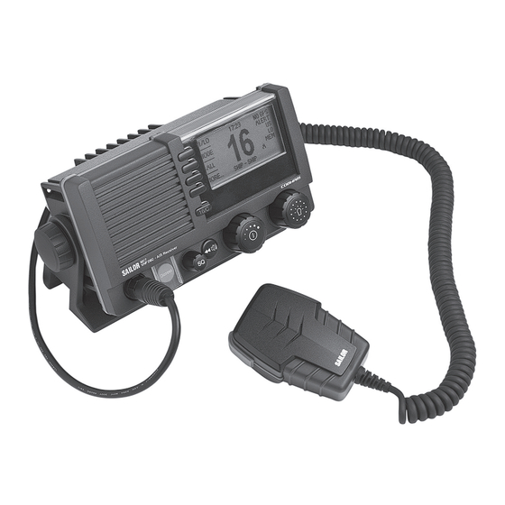
You can use the loudhailer as a 2-way on-board communicator. The loudhailer also functions as a fog horn. You can select from several programmed fog-horn patterns. For a list of other accessories available for the SAILOR 6217 VHF DSC - AIS Receiver check with your nearest distributor. - Page 14 Chapter 1: Introduction Controls on the front plate 1. Loudspeaker. 2. Four soft keys with function title in the display. 3. Quick selection key for channel 16 and the programmed call channel. 4. Large display. 5. Connector for Handmicrophone or handset. If not used, put the cap from the ACC connector on the front connector to prevent water ingress.
- Page 15 Chapter 1: Introduction SAILOR 6217 VHF DSC - AIS Receiver display The picture shows the display after start-up.The display holds various fields of information, HI/LO GPS Position depending on the currently WATCH selected function. CALL 1. Action line containing MORE...
- Page 16 RX/TX Aerial SAILOR 6201 SAILOR 6205 Control Speaker Handset Microphone SAILOR 6202 Hand Microphone Service Cable SAILOR 6217 VHF DSC - AIS Receiver SAILOR 6201 Handset Option SAILOR 6207 N163S Connection Box SAILOR 6090 for parallel handsets Power Converter GPS,...
-
Page 17: Chapter 2 Operation
Chapter 2 Operation Before using the VHF radio make sure that the VHF antenna, Note power and other external equipment are connected properly. For instructions see chapter Installation on page 51. In this chapter you find detailed instructions and guidelines for: •... -
Page 18: General Use And Navigation
Chapter 2: Operation General use and navigation Power on and speaker volume The VHF radio has a dual-function on/off wheel knob for power on/off and volume control. • To power on the VHF radio press the on/off wheel knob. • To power off the VHF radio, press and hold the on/off wheel knob and follow the instructions in the display. - Page 19 Chapter 2: Operation DSC and MMSI number When the VHF radio is powered on for the first time, you must enter the vessel’s MMSI number. Hereafter the MMSI number is briefly displayed after power up. The MMSI is a unique, 9-digit identifier assigned to your ship.
- Page 20 MMSI is not programmed. Position and MMSI Information To display position and MMSI information for the SAILOR 6217 VHF DSC - AIS Receiver radio, do as follows: 1. Press the soft key POS. If it is not in the display, press the soft key MORE until POS appears.
-
Page 21: Adjusting The Squelch
Chapter 2: Operation Speaker devices The VHF radio can be equipped with the following speaking devices: • SAILOR 6202 Handmicrophone with a PTT (Push To Talk) button. • Handset with a microphone, ear piece and a PTT button. The volume in the ear piece can be adjusted, for details see Controller setup on page 10. - Page 22 Setup pages for RADIO, HAILER/FOG, SYSTEM, CONTROLLERand DSC The functions of the SAILOR 6217 VHF DSC - AIS Receiver are accessed and set using the four soft keys to the left of the display. The current function of a soft key is shown in the display next to the soft key. For some applications there are two control levels •...
- Page 23 Chapter 2: Operation Parameter Description Handset 1 vol: Adjust earpiece volume for handset 1: OFF, 1 to 14 Note: Default setting is OFF. If a handset is connected to the front connector this value must be configured to a value (1-14). Handset 2 vol: Adjust earpiece volume for handset 2: OFF, 1 to 14 Note: Default setting is OFF.
-
Page 24: Vhf Radio Communication
Chapter 2: Operation VHF radio communication In this section of the manual you find information on • Basic VHF operation • VHF channels • Programming a call channel • Naming a channel Basic VHF operation You can make VHF calls using the Handmicrophone or another speaking device. - Page 25 Chapter 2: Operation 3. Press the PTT key. A TX symbol shows that the radio is transmitting on the channel displayed. 4. Repeat the name of the station calling you and say: “This is [your ship’s name]”. 5. Suggest a working channel other than 16 by saying: “Channel [suggested channel number]”.
- Page 26 Chapter 2: Operation VHF channels You can change channels whenever the channel designator is displayed. Turn the selector wheel knob to browse through all channels that are available in the selected channel mode. The channels appear in the display in the following order: •...
- Page 27 Chapter 2: Operation Programming a call channel To program a call channel (or quick selection), do as follows: 1. Make an extra-long press (2.5 s duration) on the 16/C key. 2. Press the soft key CALL CH. The channel designator is flashing.
- Page 28 Chapter 2: Operation Display for non-VHF applications When the radio is used for functions other than VHF, the display is arranged differently. The large channel display moves to the bottom line along with selected icons. The channel displayed in this line will always reflect the communication channel on which the radio is tuned into for communication.
-
Page 29: Hi/Lo Transmission Power
Chapter 2: Operation HI/LO transmission power Press the soft key HI/LO to toggle the transmit power between low (1 W) and high (25 W). If LO is not displayed, the transmit power is HI. US channels: Local mode, 10 dB attenuation To attenuate to the incoming signal, do as follows: 1. -
Page 30: Watch
Chapter 2: Operation Watch The SAILOR 6217 VHF DSC - AIS Receiver radio can be set to dual watch or triple watch. In dual watch, the working channel and channel 16 are watched. In triple watch the working channel, channel 16 and the programmed call channel are watched. -
Page 31: Scan
Chapter 2: Operation Scan The radio has a scanning function for tagged channels. Any available channel, including weather and private channels, can be tagged and added to the scanning sequence. As default the radio scans with priority scanning of channel 16. If a signal is received while in any scanning mode, only channel 16 continues to be watched. - Page 32 Chapter 2: Operation US channels: Watch alarms for NOAA Weather alerts NOAA weather channels are available in the waters of USA and Note Canada only. You can turn on or off an independent watch alarm for a specific weather channel. To turn on or off an independent NOAA weather alarm do as follows: 1.
-
Page 33: Radio Setup
Chapter 2: Operation Radio setup In the RADIO SETUP you set scan and watch mode, select the channel table and can set and view the ATIS code. To change a setting in the RADIO SETUP, do as follows: 1. Press the soft key SETUP. If it is not in the display, press the soft key MORE until SETUP appears. - Page 34 Chapter 2: Operation Para- Description meter Priority ON: All channels tagged for scanning are scanned while monitoring Scan channel 16. (default). OFF: Only the channels tagged for scanning are scanned in sequence, not channel 16, unless it is tagged for scanning. To select the channel table for the primary channel.
- Page 35 Chapter 2: Operation Para- Description meter ATIS The ATIS code (Automatic Transmitter Identification System) is code used for identification to marine coast and inland stations and its use is mandatory in a number of European inland waterways such as e.g. the river Rhine. Like the MMSI number the ATIS number is issued by the relevant authority.
-
Page 36: Dsc Calls
Chapter 2: Operation DSC calls In this section of the manual you find information on: • Sending, acknowledging and cancelling own distress • Receiving distress calls • DSC calls for communication • DSC setup Sending, acknowledging and cancelling own distress To send a distress message To send a distress message do as follows: 1. - Page 37 Chapter 2: Operation Having pressed the red distress button and sent the distress message, press the soft key INFO to display further information: • STATION: shows the radio’s MMSI number. • NAT: shows the nature of distress, see also To (Example) send a distress message with specified nature on page 25.
- Page 38 4. Then lift the cover of the red distress button and push the Distress button for 3 seconds. To acknowledge own distress When the SAILOR 6217 VHF DSC - AIS Receiver receives an acknowledgement of distress from another vessel or station, a 2-tone alarm sounds.
- Page 39 At this stage you have the option to press the soft key NO to return to distress sending procedure. 3. The SAILOR 6217 VHF DSC - AIS Receiver will send the Self- cancellation call on channel 70 and the display automatically shows the message that you should say when cancelling the distress with a radio message.
- Page 40 Chapter 2: Operation Power failure while in distress In case of a power failure or switch-off during the transmission of a Distress the SAILOR 6217 VHF DSC - AIS Receiver gives an audible warning after power-up and automatically resumes sending Distress 10 seconds after power up.
- Page 41 Chapter 2: Operation key SILENT. A press on any other key also switches off the 2-tone alarm.any key. Distress call with errors If a distress call contains errors, it is still received and errors in the data are shown as underscores (_).
- Page 42 Chapter 2: Operation DSC calls for communication With a DSC call you can establish a radio communication with one or several specific radios on a suggested VHF channel. To make a DSC call for communication, do as follows: 1. Press the soft key CALL. The default call is an individual routine call.
- Page 43 Chapter 2: Operation • Press and turn the selector wheel knob to change the suggested VHF channel for following communication. 3. Press the soft key SEND to make the call. Sessions A DSC session (or automated procedure) is defined as a collection of DSC calls (transmitted and/or received) that are related to the same event (e.g.
- Page 44 Chapter 2: Operation 3. The MMSI number of the other party, if contact to a specific station or group shall be established. 4. Elapsed time since the reception of a call request or an acknowledgement. 5. Session state: • (ACTIVE) — transmitter tuned into the communication channel. •...
- Page 45 Chapter 2: Operation Soft keys to control DSC sessions Call/session types vary in control options, and options may also change if a session changes its state. The following table gives an overview of the DSC soft key commands available: Soft key Radio function QUIT Terminates the DSC session...
- Page 46 Chapter 2: Operation Soft key Radio function ANNUL Cancels an inadvertently transmitted distress (Cancel Own Distress) Confirms action and proceed sequence, used in CONFIRM cancel distress procedure (Cancel Own Distress) Turns page of text message. INFO (in Cancel Own Distress) A filtered version of the log displaying received calls LOG (Received relevant to the current distress event.
- Page 47 Chapter 2: Operation Detail information for DSC sessions (soft key: INFO) A DSC session is updated based on DSC calls received or transmitted. Press the soft key INFO to show the details for the current session. For distress events a sequence of calls may contribute to the complete view and status of the session.
-
Page 48: Receiving Dsc Calls
Chapter 2: Operation Receiving DSC calls If the radio is IDLE (not engaged in another session) and a DSC call is received the call details are shown on the display. The following options (soft keys) are available: Soft key Radio function The call is acknowledged immediately and the radio is (individual) afterwards tuned to the communication channel (if any... - Page 49 Chapter 2: Operation If a DSC session is put on HOLD it is automatically put in the background (VHF communication display appears on the previous communication channel). The soft key is used to toggle between the VHF communication and a DSC session on hold.
-
Page 50: Dsc Setup
Chapter 2: Operation DSC call logs To display a DSC call log in the DSC CALL LOGS, do as follows: 1. Press the soft key SETUP. If it is not in the display, press the soft key MORE until SETUP appears. to advance to DSC CALL LOGS. - Page 51 Chapter 2: Operation DSC setting Description Position Info Available position information. Here you can enter position data, see also Position and MMSI Information on page 8. Auto-Ack Test Auto-acknowledgement of test DSC messages OFF - Disabled ON – Enabled (default) Auto-Ack Auto acknowledgement of individually addressed, Individual...
- Page 52 Chapter 2: Operation DSC setting Description Auto-switch Enable automatic channel switching on reception Channel of DSC calls with subsequent communication channel information, while the radio is not engaged (for calls other than individual station calls of category distress or urgency). ON (default) OFF - LCK icon indicates that the channel is locked and must be selected manually...
-
Page 53: Phone Book
Chapter 2: Operation Phone book Use the phone book when making a DSC call. You can enter up to 50 contacts. A contact has the following details: • Name (up to 20 characters) • Type (SHIP, GROUP or COAST STATION) •... - Page 54 Chapter 2: Operation Adding a contact to the phone book To add a contact to the phone book do as follows: 1. Press the soft key PHBOOK. If it is not in the display, press the soft key MORE until PHBOOK appears in the display. 2.
- Page 55 Chapter 2: Operation Editing a contact 1. Press the soft key PHBOOK. If it is not in the display, press the soft key MORE until PHBOOK appears. 2. Press the soft key EDIT. 3. Press and turn the selector wheel knob to browse through the details of the contact.
-
Page 56: Loudhailer With Talk-Back
Chapter 2: Operation Loudhailer with talk-back The SAILOR 6217 VHF DSC - AIS Receiver supports a loudhailer with a talk- back function. When the hailer is in talk-back mode and a radio signal is Important received, the radio signal has a higher priority and is heard in the loudspeaker. -
Page 57: Automatic Foghorn
Chapter 2: Operation Automatic foghorn The SAILOR 6217 VHF DSC - AIS Receiver has an automatic fog horn application with several foghorn patterns. Once started, it runs in the background while running any other application. The fog horn may be combined with the loudhailer talk-back mode. - Page 58 Chapter 2: Operation 2. Use the selector wheel knob to browse through the patterns available. 3. Press the selector wheel knob at the wanted pattern to accept the pattern. 4. To deactivate the foghorn, turn the selector wheel knob to browse to OFF and press the selector wheel knob.
-
Page 59: Hailer And Fog Horn Setup
Chapter 2: Operation Hailer and Fog horn setup To change a setting in the HAILER/FOGHORN SETUP, do as follows: 1. Press the soft key SETUP. If it is not in the display, press the soft key MORE until SETUP appears. to advance to HAILER/FOGHORN 2. -
Page 60: Replay Function
Chapter 2: Operation Replay function Replay allows the operator to playback received voice messages in the loudspeaker. Recording is activated automatically when a signal is received. Recording is not possible during playback. Up to 60 tracks or 90 seconds can be handled. The recorded channel is displayed. -
Page 61: Ais On A Connected Chart Plotter
Chapter 2: Operation AIS on a connected chart plotter The AIS receiver receives data as soon as the VHF radio is switched on. If equipment supporting AIS data over NMEA is attached to the VHF radio, it starts plotting the targets received. AIS information transmitted from vessels with class A and B transponders includes static and dynamic information. - Page 62 Chapter 2: Operation AIS on a connected chart plotter...
-
Page 63: Chapter 3 Installation
• Power, VHF antenna and external equipment Unpacking the SAILOR 6217 VHF DSC - AIS Receiver The following items are included in the delivery of a SAILOR 6217 VHF DSC - AIS Receiver: • SAILOR 6217 VHF DSC - AIS Receiver •... -
Page 64: Installing The Vhf Radio
Provide space enough to access the front panel connectors and for installing a cradle for the speaking device. Provide at least 120 mm space at the back of the SAILOR 6217 VHF DSC - AIS Receiver radio to allow free air circulation. - Page 65 Chapter 3: Installation SAILOR 6217 VHF DSC - AIS Receiver with U mounting bracket The mounting bracket and two knobs are included in the delivery. Desktop mounting Installing the VHF radio...
- Page 66 Chapter 3: Installation Overhead mounting Installing the VHF radio...
- Page 67 Chapter 3: Installation Mounting with U mounting bracket To mount the VHF radio as tabletop, do as follows: 1. Find a suitable location for the VHF radio. Check that the space is wide/deep enough to accommodate the VHF radio. 2. Fasten the bracket with 4 screws (included in the delivery.)
- Page 68 Chapter 3: Installation SAILOR 6217 VHF DSC - AIS Receiver for flush mount You can mount the VHF radio to a flat surface, e.g. an instrument panel.The flush mount installation kit is included in the delivery. R2.5mm x 4 177mm Remove material from shaded area only! The scaling in the above drawing is not 1:1.
- Page 69 Chapter 3: Installation 2. Keep free distance to allow free air circulation around the VHF radio and to allow sufficient space for access to cables, see the drawing on this page. 3. Cut out the hole for the VHF radio where you want to mount it. Use the cutting template in the installation guide.
- Page 70 Chapter 3: Installation SAILOR 6202 Handmicrophone Handmicrophone with spiral cable and PTT button. Installing the VHF radio...
-
Page 71: Power, Vhf Antenna And External Equipment
Chapter 3: Installation Power, VHF antenna and external equipment 1. ACC connector for accessories 2. CTRL connector for control speaker microphone 3. Power, Loudhailer, foghorn and external speaker 4. VHF antenna 5. Ground stud Power, VHF antenna and external equipment... - Page 72 Chapter 3: Installation ACC connector Use the connector marked ACC to connect GPS input and/or a chart plotter that supports AIS. The interface for GPS is NMEA 0183 (EN61 162-1 NMEA0183/ EN61 162-2 NMEA0183 Highspeed). To connect a chart plotter that supports AIS, connect the NMEA output wires from the VHF radio to the NMEA input on the chart plotter.
- Page 73 Chapter 3: Installation Connector type: Circular connector, 10pin. Connection cable with plug, part number 406209-941. Pin assignment: Connector front view on the VHF radio Description Wire color NMEA in+ Brown NMEA in- Blue NMEA out- White NMEA out+ Green Mike 2 Yellow EAR 2 Grey...
-
Page 74: Specifications
Chapter 3: Installation NMEA interface description NMEA Specifications interface Impedance: 600 Ohm NMEA input: Max. 2mA at min. level of 2V Load Impedance: > 60 Ohm NMEA output Drive load: < 35 mA The NMEA interface supports NMEA 0183 v2.0, v2.1 and v2.3. The following sentences are supported: Power, VHF antenna and external equipment... - Page 75 Chapter 3: Installation • FSI: All fields are decoded. • GGA: UTC, "Position", "quality indicator" (indicators 1-5). All other fields are unused. • GLL: UTC, "Position", "Status" and "mode" (indicators A and D). All other fields are unused. • GNS: UTC, "Position" and "mode" (indicators A and D). All other fields are unused.
- Page 76 Chapter 3: Installation CTRL connector for control speaker microphone Connector type: Circular connector, 12pin. Pin assignment: Connector front view on the VHF radio: Description Description GND for cable screen Internal GND = - Battery Internal GND=- Battery not used Battery supply when radio is on RX out + Battery supply when radio is on 10 RX out - CAN+...
- Page 77 Chapter 3: Installation Power, Loudhailer, foghorn and external speaker Use the connector marked PWR/EXT to connect power, loudhailer and an external speaker. The cable for this connector is part of the delivery. 1. Blue wire: Power - 2. Red isolation on inner connector: loudhailer 3.
-
Page 78: Vhf Antenna
Chapter 3: Installation Protection against water ingress You must protect the cable connection with rubber vulcanizing Important tape as shown in the pictures below. This protection prevents water seeping into the VHF radio, cable and connectors. VHF antenna Use the connector marked ANT to connect the VHF antenna to the radio with a 50 Ohm coaxial cable with low loss, e.g. -
Page 79: System Setup
Chapter 3: Installation System setup To change a setting in the SYSTEM SETUP, do as follows: 1. Press the soft key SETUP. If it is not in the display, press the soft key MORE until SETUP appears. to advance to SYSTEM SETUP. 2. -
Page 80: Sailor 6201 Handset Cradle (Optional)
Chapter 3: Installation SAILOR 6201 Handset cradle (optional) Drilling plan * 120 Space for handset access This Handset has a hook-on/off function, which is activated by a small magnet embedded in the cradle. The cradle must be installed as illustrated in order to ensure the hook-on/off functionality of the Handset. -
Page 81: Chapter 4 Service & Maintenance
Maintenance Preventive maintenance Maintenance of the SAILOR 6217 VHF DSC - AIS Receiver can be reduced to a maintenance check at each visit of the service staff. Inspect the radio for mechanical damages, salt deposits, corrosion and any foreign material. - Page 82 Chapter 4: Service & maintenance DSC self test To run a control routine DSC self test, do as follows: 1. Press the soft key SETUP. If it is not in the display, press the soft key MORE until SETUP appears. to advance to DSC SETUP.
-
Page 83: Troubleshooting Guide
Chapter 4: Service & maintenance Troubleshooting guide Action Symptom Remedy The radio will The display is Check if power is present. not turn on empty. Check fuse which is placed in the + supply wire. Check performance of power supply if connected to one. - Page 84 Chapter 4: Service & maintenance Action Symptom Remedy DSC routine Check the DSC function regularly. Verify the testing complete DSC installation, with antennas, by transmitting a Safety Test call to another station (coast or ship). The test call is generated using the DSC call flow via menu CALL.
- Page 85 Chapter 4: Service & maintenance Action Symptom Remedy Radio time DSC logs are A wrong radio time indication should occur sorted with only if GPS position source is not connected wrong time or providing correct time data. A valid GPS stamp or radio time signal will update the UTC time used for time is...
- Page 86 Chapter 4: Service & maintenance Action Symptom Remedy Device failure If any of the checks and tests described in this section do not assist in resolving the difficulties experienced in the operation and/or performance of the VHF installation, a fault may have developed in the VHF radio itself.
-
Page 87: Warranty
Chapter 4: Service & maintenance Replacing the fuse in the red wire (Power +) One fuse is installed in the supplied DC cable. If the fuse is blown, track down why the fuse was blown and solve the problem. To replace the fuse, do as follows: 1. - Page 88 Chapter 4: Service & maintenance Warranty...
-
Page 89: Technical Specifications
Appendix A Technical specifications Item Specification Weight SAILOR 6217 VHF DSC - approx. 1.2 kg AIS Receiver Weight SAILOR 6217 VHF DSC - approx. 1,5 kg including SAILOR 6202 AIS Receiver and Handmicrophone and mounting bracket Handmicrophone Height: Outer dimension 106 mm, hole... - Page 90 Appendix A: Technical specifications Item Specification Number of P channels The radio may be programmed with up to 40 private channels that can be managed in all channel modes. Transmit power Hi/Lo: 25 W and <1 W RF output power 25 W +0 dB / - 1.5 dB 1 W +0 dB / - 1.5 dB Modulation...
- Page 91 Chapter A: Technical specifications NMEA data rates and formats Item Value 61162-1 4800,8,n,1 (in/out) 61162-2 38400,8,n,1 (out only) Sentence format !AIVDM...
- Page 92 Chapter A: Technical specifications...
-
Page 93: Maritime Channels
Appendix B Maritime channels International channels Channels SIMPLEX DUPLEX Channels SIMPLEX DUPLEX Intership Port Port Public Intership Port Port Public 156,050 160,650 156,025 160,625 156,100 160,700 156,075 160,675 156,150 160,750 156,125 160,725 156,200 160,800 156,175 160,775 156 250 160 850 156,250 160,850 156 225 160 825 156,225 160,825... - Page 94 Appendix B: Maritime channels US channels Channels SIMPLEX DUPLEX Channels SIMPLEX DUPLEX Channels 156,050 156,050 162,550 162,400 162,475 156,175 156,175 162,425 156,250 156,250 162,450 156,300 156,300 156,275 156,275 162,500 156,350 156,350 156,325 156,325 162,525 156,400 156,400 156,375 156,375 156,450 156,450 156,425 156,425 156,500 156,500 156,475 156,475...
- Page 95 Appendix B: Maritime channels Ca channels Channels SIMPLEX DUPLEX Channels SIMPLEX DUPLEX Channels 156,050 160,650 156,025 160,625 162,550 156,100 160,700 156,075 156,075 162,400 156,150 160,750 156,125 156,125 162,475 156,200 156,200 156,175 156,175 162,425 156,250 156,250 156,225 160,825 162,450 156,300 156,300 156,225 156,225 162,500 156,350 156,350...
- Page 96 Appendix B: Maritime channels Bi channels Channels SIMPLEX DUPLEX Channels SIMPLEX DUPLEX Intership Port Port Public Intership Port Port Public 156,050 160,650 156,025 160,625 156,100 160,700 156,075 160,675 156,150 160,750 156,125 160,725 156,200 160,800 156,175 160,775 156,250 160,850 156,225 160,825 156,300 156,300 156,275 160,875 156,350 160,950...
-
Page 97: Declaration Of Conformity
Appendix C Declaration of conformity The SAILOR 6217 VHF DSC - AIS Receiver is certified as stated in the “Declaration of Conformity with R&TTE Directive, enclosed in copy on the next page. - Page 98 Appendix C: Declaration of conformity...
-
Page 99: Glossary
Glossary Glossary Accessories Automatic Identification System, a short range coastal tracking system used on ships and by Vessel Traffic Services for identifying and locating vessels by electronically exchanging data with other nearby ships. AIVDM NMEA sentences for AIS data, !AIVDM stands for Received Data from other vessels. - Page 100 Glossary International Maritime Organization NMEA National Marine Electronics Association, specification for communication between marine electronic devices Push To Talk Power NMEA sentence, version of essential gps position, velocity, time data. Coordinated Universal Time. The International Atomic Time (TAI) with leap seconds added at irregular intervals to compensate for the Earth’s slowing rotation.
-
Page 101: Index
Index Index Numerics 16/C, 12 background sessions 90 s replay, 48 DSC, 36 backlight, 1 dim, 6 Bi, 84 Bi channels, 84 ACC connector, 60 browse channels, 6 acknowledgement, distress, 26 action line, display, 3 activate foghorn, 41, 45 scan resume, 21 Ca channels, 83 scanning, 19 cable for VHF antenna, 66... - Page 102 Index channel table ALT, 22, 84 data rate Bi, 84 NMEA, 79 Ca, 83 deactivate, 46 CAN, 22 foghorn, 46 INT, 81 watch, 18 PRIV, 22, 84 Declaration of Conformity, 85 US, 22, 82 default reset, 67 channels DELETE, 43 Bi, 84 delete contact, 43 Ca, 83...
- Page 103 Index dual watch, 21 change to triple, 18 HAIL, 44 hand microphone installing, 58 Handmicrophone, 9 editing a contact, 43 handset cradle emergency calls, iv installation, 68 enter position manually, 8 hang time, 21 error messages, 69 headline external speaker DSC, 32 cabling, 65 HORN, 46...
- Page 104 Index louder, volume, 6 Non-dist Inactivity, 39 loudhailer, 1 Non-distr.alarms, 39 connector, 65 receiving radio channel, 44 low power override, 17 overriding low power, 17 low power, overriding, 17 manual, document number, i talk-back, 44 maritime channels, 81 password, 67 MAYDAY, iv PHBOOK, 41 message...
- Page 105 Index setup AIS, 67 radio call controller, 10 making, 13 foghorn frequency, 47 receiving, 12 Radio, 21 radio channel, loudhailer, 44 system, 67 received distress calls, 28 watch, 21 replay, 1, 48 simplex, 1 button, 2 soft key reset to default, 67 ADD, 42 resume time, 21 CALL, 41...
- Page 106 Index system configuration volume example, 4 louder, 6 system setup, 67 softer, 6 speaker, 6 Volume wheel knob, 2 TAG, 19 remove, 19 talk back, 47 warnings, 69 technical data, 77 warranty temperature limitation, iii operational, 77 WATCH, 18, 19 storage, 77 watch testing, foghorn, 46...
- Page 108 98-130645-THR-E www.cobham.com/satcom...
Need help?
Do you have a question about the SAILOR 6217 and is the answer not in the manual?
Questions and answers