Table of Contents
Advertisement
Quick Links
Advertisement
Table of Contents

Related Manuals for COBHAM SAILOR 6248 VHF


Summary of Contents for COBHAM SAILOR 6248 VHF
- Page 1 SAILOR 6248 VHF User manual...
- Page 3 SAILOR 6248 VHF User manual Document number: 98-131186-G Release date: January 7, 2014...
- Page 4 December 31, 2015, by sending a money order or check for DKK 50 to: SW Technology/GPL Compliance, Thrane & Thrane A/S, Lundtoftegaardsvej 93D 2800 Lyngby DENMARK Please write "source for product SAILOR 6248 VHF" in the memo line of your payment. This offer is valid to anyone in receipt of this information.
- Page 5 Warranties Any attempt to install or execute software not supplied by Thrane & Thrane on this device will result in the warranty being void. Any attempt to modify the software on this device in a way not specified by Thrane & Thrane will result in the warranty being void.
-
Page 6: Compass Safe Distance
Thrane & Thrane assumes no liability for the customer's failure to comply with these requirements. Ground the equipment To minimise shock hazard, the SAILOR 6248 VHF unit must be connected to an electrical ground and the cable instructions must be followed. RF exposure hazards and instructions Your Thrane &... - Page 7 Alerte de sécurité Dangers liés à l'exposition aux fréquences radio et instructions Conformément à la réglementation d'Industrie Canada, le présent radio émetteur ne peut fonctionner qu'avec une antenne de type omnidirectionnelle, demi-onde ou d'un gain maximal de 4 dB, approuvée par Industrie Canada.
-
Page 8: Emergency Calls
Emergency calls Make sure your VHF Radio is on CH16 Press Press Use the HANDSET or SPEAKER MICROPHONE for voice calling MAYDAY-MAYDAY-MAYDAY OWN ID This is SHIP‘s NAME: NAME-NAME-NAME CALLSIGN CALLSIGN: or other IDENTIFICATION MAYDAY NAME of the VESSEL in distress CALLSIGN or other IDENTIFICATION POSITION given as latitude and longitude... - Page 9 SAILOR 6248 VHF is designed for occupational use only and must be operated by licensed personnel only. SAILOR 6248 VHF is not intended for use in an uncontrolled environment by general public. SAILOR 6248 VHF is designed for installation by a skilled service...
- Page 10 Training information The SAILOR 6248 VHF is designed for occupational use only and is also classified as such. It must be operated by licensed personnel only. It must only be used in the course of employment by individuals aware of both the hazards as well as...
- Page 11 Installation 1. An omni-directional antenna with a maximum power gain of 4 dB must be mounted at least 400 cm above the highest deck where people may be staying during radio transmissions. The distance is to be measured vertically from the lowest point of the antenna.
-
Page 12: Manual Overview
Related documents Document Title and description number SAILOR 6248 VHF, Installation guide 98-132282 SAILOR 6248 VHF, Installation manual 98-133233 (download only) Emergency call sheet 98-133795... -
Page 13: Table Of Contents
Contact for support ................27 Maintenance ..................27 Troubleshooting guide ..............28 Warranty and returning units for repair ........31 App. A Specifications Transceiver unit SAILOR 6248 VHF .......... 33 SAILOR 6090 Power Converter 24—12 V ......35 Approval ....................37... - Page 14 Table of Contents App. B Maritime channels International channels (INT) ............39 US channels ..................40 CA channels ..................41 BI channels ................... 42 Glossary ........................43 Index ........................45...
-
Page 15: Chapter 1 Introduction
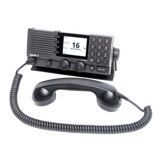
R&TTE and is waterproof to the IPx8 and IPx6 standard. As part of the required safety equipment, use the SAILOR 6248 VHF in an emergency situation. However the best way to guarantee functionality in an emergency situation, is to use the radio in daily communication on board. - Page 16 Chapter 1: Introduction Controls on the front plate 1. Loudspeaker. 2. Four soft keys with function title in the display. 3. Large display. 4. Keys 0 to 9 to enter numbers or text. 5. DW button to toggle the watch function (dual or triple). 6.
- Page 17 Chapter 1: Introduction SAILOR 6248 VHF display The picture shows the display after start-up. The display holds various fields of information, LOC LO SCAN depending on the currently selected function. PHBOOK 1. Functions you can select with LOCAL the soft keys.
-
Page 18: Accessories Available
SAILOR 6201 One SAILOR 6201 Handset with Handset with cradle cradle is included in the delivery (additional) of the SAILOR 6248 VHF. You can connect another SAILOR 6201 Handset with cradle. SAILOR 6203 SAILOR 6203 Handset with Handset with cradle cradle, waterproof to IPx6. - Page 19 406204-940). 5m Connection cable, 1x10 pole: Use this cable in installations when connecting external equipment to the SAILOR 6248 VHF. This cable is included in the SAILOR 6207 Connection Box for parallel Handsets (part number: 406207-941). 5 m Connection cable for SAILOR 6204 Control Speaker Microphone, 1x12 pole (part number: 406204-940).
- Page 20 Chapter 1: Introduction System configuration — example The SAILOR 6248 VHF can be customized to suit your installation. The following illustration is one example of a system. For further configuration examples see the installation manual, Appendix B, System configurations. RX/TX...
-
Page 21: Chapter 2 Operation
Note Before using the VHF radio make sure that the VHF, power cable and other external equipment are connected properly. For installation instructions see the SAILOR 6248 VHF, Installation manual (download only). Overview In this chapter you find detailed instructions and guidelines for: •... -
Page 22: General Use And Navigation
Chapter 2: Operation General use and navigation Power on and volume in handset and speaker The VHF radio has a dual-function on/off knob for power on/off and volume control. To power on the VHF radio press the on/off knob. To power off the VHF radio, press and hold the on/off knob and follow the instructions in the display. - Page 23 Chapter 2: Operation Speaker devices The VHF radio can be equipped with the following speaker devices: • TT-6201A/TT-6203A Handset with cradle and PTT (Push To Talk) button. • TT-6202A Hand Microphone with PTT button. • TT-6204A Control Speaker Microphone with PTT button. See Controller setup on page 24 for controlling the connected speaker devices.
-
Page 24: Adjusting The Squelch Level
Chapter 2: Operation Changing the display light, night view Red text on black background is available for optimal night vision. To dim the display backlight, e.g. to give comfortable night vision, press, hold and turn the selector knob anti-clockwise. The display shows a brightness bar. -
Page 25: Vhf Radio Communication
Chapter 2: Operation VHF radio communication Basic VHF operation You can make VHF calls using the Handset or another speaker device. A single, short press on the 16/C key always brings you to Note channel 16, the international calling and distress channel, no matter what state the radio is in. - Page 26 Chapter 2: Operation 7. Switch to the new channel using the keypad or by turning the selector knob to the agreed channel and begin your conversation. Press PTT only when you are talking. Making a radio telephone call on channel 16 To make a radio telephone call, proceed as follows: 1.
- Page 27 Chapter 2: Operation VHF channel Description table Primary channels For details see Maritime channels on page 39. For (no prefix) instructions how to change a channel table see Channel setup on page 22. Weather channels have the prefix W. (For US and Weather (WX) CA channels only.) Private (PRIV)
-
Page 28: Watch
Chapter 2: Operation Note Local mode is automatically exited when selecting channel 16 by pressing 16/C button. If you want to use attenuation on channel 16 or a call channel, you must set it manually each time. US channels: Overriding LOW power for channels 13 and 67 When running in US mode you can override low power on the alternative call channels 13 and 67. -
Page 29: Scan
Chapter 2: Operation Scan The radio has a scanning function for tagged voice channels. Any available voice channel, including weather and private channels, can be tagged and added to the scanning sequence. As default the radio scans with priority scanning of channel 16. If a signal is received while in any scanning mode, only channel 16 continues to be watched. -
Page 30: Phone Book
Chapter 2: Operation Phone book You can enter up to 200 contacts. A contact has the following details: • Name (up to 12 characters) • Type (SHIP, GROUP or COAST STATION) • Channel The phone book is always sorted alphabetically by contact names. Use the soft key FILTER to toggle between CONTACTS - ALL, COAST, SHIP or GROUP. - Page 31 Chapter 2: Operation 3. Press the soft key SAVE to save the contact information. 4. Press the soft key EXIT to leave the phone book. Editing a contact 1. Press the soft key PHBOOK. 2. Select the contact. 3. Press and turn the selector knob to browse through the details of the contact and continue as described in Adding a contact to the phone book from step 2 onwards.
-
Page 32: Replay Function
Chapter 2: Operation Deleting a contact 1. Press the soft key PHBOOK. 2. Turn the selector knob to browse to the contact you want to delete. 3. Press the soft key DELETE. 4. Press EXIT to leave the phone book and return to VHF operation. Replay function Replay allows the operator to playback received voice messages in the loudspeaker. -
Page 33: Setup
Chapter 2: Operation Setup The following setup pages are described in this section of the manual: • Radio setup • Channel setup • Power Supply • System setup • Controller setup Accessing a setup page To change a setting in one of the SETUP pages, do as follows 1. - Page 34 Chapter 2: Operation Parameter Description Scan Scan resume time, in seconds. When the programmed time of Resume inactivity has elapsed, and when watch/scan has been aborted using a press on PTT, or after power-up, scan or watch is resumed. OFF: Automatic resume is deactivated (default) 3, 6, 10, 15, 20, 25, 30: Resume time in seconds.
- Page 35 Chapter 2: Operation a. The Committee Rainwat in its 12. Meeting (October 2008) decided to change the building rules of the ATIS code for vessels coming from a country outside the RAINWAT arrangement. Setup...
- Page 36 Chapter 2: Operation Channel setup Parameter Description Channel Mode To select the channel table for the primary channel. Channel tables available: INT, BI, US, CA, ALT. See also VHF channel table on page 13. Bandwidth Selection of the bandwidth for the fixed pre-programmed channels.
-
Page 37: Power Supply
Chapter 2: Operation Parameter Description US. Channels As described above. CA. Channels As described above. ALT. Channels As described above. Private As described above. Channels Power Supply Paramete Description Monitor Set this to ENABLED if the radio is connected to a TT-6081A Power Supply and Charger. - Page 38 Chapter 2: Operation SYSTEM SETUP Description Theme Changes the display colour. BlackOnWhite (default) WhiteOnBlack Factory Defaults Resets the radio to factory defaults. Press the selector knob and confirm the reset to factory default. Radio Info: SW Version: Software version of the radio S/N: Serial number of the radio IP: IP address of the radio Password...
- Page 39 Chapter 2: Operation Controlling Description device Wheel lock: You can set a time interval after which the SQ, volume and selector knobs are locked and protected against unintentional use. Then a lock symbol is shown in the display. Press any key to unlock the knobs. OFF, 10s, 20s, 30s, 40s, 50s, 60s Top-level standby soft-key functions and setup pages Top-level standby...
- Page 40 Chapter 2: Operation Setup pages RADIO SETUP Scan Hang Time Scan Resume Watch mode Priority Scan ATIS code CHANNEL SETUP Channel Mode Bandwidth Call Channel Int. Channels BI. Channels US. Channels CA. Channels ALT. Channels Private Channels POWER SUPPLY Monitor SYSTEM SETUP System time &...
-
Page 41: Chapter 3 Service & Maintenance
Maintenance Preventive maintenance Maintenance of the SAILOR 6248 VHF can be reduced to a maintenance check at each visit of the service staff. Inspect the radio for mechanical damages, salt deposits, corrosion and any foreign material. Due to its robust construction and ruggedness the radio has a long lifetime. -
Page 42: Troubleshooting Guide
Chapter 3: Service & maintenance Troubleshooting guide Action Symptom Remedy The radio The display Check if power is present. will not turn is empty. Check fuse which is placed in the power connector. Check performance of power supply if connected to one. - Page 43 Chapter 3: Service & maintenance Replacing the fuse in the power connector One fuse is installed in the power connector. If the fuse is blown, do as follows: 1. Track down why the fuse was blown and solve the problem. 2.
- Page 44 Chapter 3: Service & maintenance Replacing the fuse in the SAILOR 6090 Power Converter One fuse is installed in the SAILOR 6090 Power Converter. If the fuse is blown, do as follows: 1. Track down why the fuse was blown and solve the problem. 2.
-
Page 45: Warranty And Returning Units For Repair
Your dealer, installer or Cobham SATCOM partner will assist you whether the need is user training, technical support, arranging on-site repair or sending the product for repair. Your dealer, installer or Cobham SATCOM partner will also take care of any warranty issue. Repacking for shipment Should you need to send the product for repair, please read the below information before packing the product. - Page 46 Chapter 3: Service & maintenance 4. Seal the shipping container securely. 5. Mark the shipping container FRAGILE to ensure careful handling. Failure to do so may invalidate the warranty. Warranty and returning units for repair...
-
Page 47: Transceiver Unit Sailor 6248 Vhf
Appendix A Specifications Transceiver unit SAILOR 6248 VHF Item Specification Weight SAILOR 6248 VHF < 1.50 kg (3.3 lbs) approximately Box weight 3.8 kg (8.4 lbs) approximately, including SAILOR 6248 VHF SAILOR 6201 Handset with cradle and wall mount cradle, SAILOR 6204 Control Speaker Microphone and Installation and user manual in box. - Page 48 High: 21 W ±0.75 dB Low: 0.8 W ±0.75 dB Frequency error Below 500 Hz Adjacent channel power Below 75 dB Below 0.25 W Conducted spurious emission Distortion Below 3% S/N ratio Better than 46 dB Transceiver unit SAILOR 6248 VHF...
-
Page 49: Sailor 6090 Power Converter 24-12 V
Appendix A: Specifications Item Specification Receiver Sensitivity < -119 dBm typically @ 20 dB SINAD CCITT weighted LF power Built-in loudspeaker: 6 W (at 5 kHz dev./1 kHz tone). External loudspeaker: 6 W / 8 Ohm Distortion Below 5% S/N ratio Better than 43 dB Spurious emissions Below 2 nW... - Page 50 Appendix A: Specifications Item Description Storage temperature -30°C to 80°C (-22°F to 176°F) Input voltage 21—32 VDC Output voltage 12.5 VDC Output current (max.) SAILOR 6090 Power Converter 24—12 V...
-
Page 51: Approval
Chapter A: Specifications Approval Declaration of Conformity The SAILOR 6248 VHF complies with the specifications of EC directive 1999/5/EC concerning Radio & Telecommunications Terminal Equipment, enclosed in electronic copy on the next page. Approval... - Page 52 Thrane & Thrane A/S Lundtoftegårdsvej 93D, DK-2800 Kgs. Lyngby, Denmark Porsvej 2, DK-9200 Aalborg SV, Denmark Place and Date Aalborg, 2nd May 2013 Svend Åge Lundgaard Jensen Document number: 99-133814-D Thrane & Thrane A/S trading as Cobham SATCOM Lundtoftegårdsvej 93D DK-2800 Kgs. Lyngby, Denmark · · ·...
-
Page 53: International Channels (Int)
Appendix B Maritime channels International channels (INT) Channels SIMPLEX DUPLEX Channels SIMPLEX DUPLEX Intership Port Port Public Intership Port Port Public 156,050 160,650 156,025 160,625 156,100 160,700 156,075 160,675 156,150 160,750 156,125 160,725 156,200 160,800 156,175 160,775 156 250 160 850 156,250 160,850 156 225 160 825 156,225 160,825... -
Page 54: Us Channels
Appendix B: Maritime channels US channels Channels SIMPLEX DUPLEX Channels SIMPLEX DUPLEX Channels 156,050 156,050 162,550 162,400 162,475 156,175 156,175 162,425 156,250 156,250 162,450 156,300 156,300 156,275 156,275 162,500 156,350 156,350 156,325 156,325 162,525 156,400 156,400 156,375 156,375 156,450 156,450 156,425 156,425 156,500 156,500 156,475 156,475... -
Page 55: Ca Channels
Chapter B: Maritime channels CA channels Channels SIMPLEX DUPLEX Channels SIMPLEX DUPLEX Channels 156,050 160,650 156,025 160,625 162,550 156,100 160,700 156,075 156,075 162,400 156,150 160,750 156,125 156,125 162,475 156,200 156,200 156,175 156,175 162,425 156,250 156,250 156,225 160,825 162,450 156,300 156,300 156,225 156,225 162,500 156,350 156,350... -
Page 56: Bi Channels
Chapter B: Maritime channels BI channels Channels SIMPLEX DUPLEX Channels SIMPLEX DUPLEX Intership Port Port Public Intership Port Port Public 156,050 160,650 156,025 160,625 156,100 160,700 156,075 160,675 156,150 160,750 156,125 160,725 156,200 160,800 156,175 160,775 156,250 160,850 156,225 160,825 156,300 156,300 156,275 160,875 156,350 160,950... -
Page 57: Glossary
Glossary Glossary Automatic Identification System, a short range coastal tracking system used on ships and by Vessel Traffic Services for identifying and locating vessels by electronically exchanging data with other nearby ships. ATIS Automatic Transmission Identification System General Public License LGPL Lesser General Public License Push To Talk... - Page 58 Glossary...
-
Page 59: Index
Index Index Numerics call channel, 12 programming, 22 16/C, 8, 11 change dual and triple watch, 14 channel add to scan, 15 bandwidth, 22 action line, display, 3 remove from scan, 15 activate select, 8, 9 scan resume, 20 working, 8, 9 scanning, 15 channel table watch, 14... - Page 60 Index handset cradle installation, 4 deactivate hang time, 19 watch, 14 how to replace, 30 default reset, 24 DELETE, 18 delete contact, 18 dim, 8 installation display, 3 cradle for 6201, 4 display colour handset cradle, 4 change, 24 installation guide, A3, x distress channel, 8, 11 installation manual, x Distress procedure, vi...
- Page 61 Index MAYDAY, vi PTT button, 11 menu, overview, 25 message replay, 18 monitor power supply, 23 radio call mute speaker, 10 making, 12 receiving, 11 reduced transmission power, 13 remote control, 10 narrow band, 22 replay, 1, 18 night vision, how to dim, 8 button, 2 reset to default, 24 resume time, 20...
- Page 62 Index simplex, 1 timeout, 23 soft key, 9 triple watch, 20 ADD, 16 change to dual, 14 DELETE, 18 FILTER, 15 OVRIDE, 14 STOP, 18 US, 40 TAG, 15 US channel table, 22, 40 WATCH, 14 UTC time, 3 softer, volume, 8 software license, ii Software version, 24 speaker volume, 8...
- Page 64 98-131186-G www.cobham.com/satcom...
Need help?
Do you have a question about the SAILOR 6248 VHF and is the answer not in the manual?
Questions and answers