Table of Contents
Advertisement
Quick Links
UHF WIRELESS TUNER
S5.5-RX
A1, B2, C1, D3
Update history
HS0910
No.833-73-817-20
TABLE OF CONTENTS
NOTE ON REPAIR WORK SAFETY ......................................................................................................... 2
SPECIFICATIONS ..................................................................................................................................... 2
NOMENCLATURE AND SET-UP .............................................................................................................. 3
BLOCK DIAGRAM ..................................................................................................................................... 4
• MAIN PCB ........................................................................................................................................... 5
• LED PCB ............................................................................................................................................. 9
• MAIN PCB ......................................................................................................................................... 10
• PARTS LIST (MAIN PCB) ................................................................................................................. 10
• LED PCB ........................................................................................................................................... 14
• PARTS LIST (LED PCB) ................................................................................................................... 14
EXPLODED VIEW AND PARTS LIST ..................................................................................................... 15
TABLE OF CONTENTS
S5.5-RX
1
Advertisement
Table of Contents

Subscribe to Our Youtube Channel
Related Manuals for Toa S5.5-RX A1


Summary of Contents for Toa S5.5-RX A1
-
Page 1: Table Of Contents
S5.5-RX TABLE OF CONTENTS NOTE ON REPAIR WORK SAFETY ......................2 SPECIFICATIONS ............................. 2 NOMENCLATURE AND SET-UP ......................3 UHF WIRELESS TUNER BLOCK DIAGRAM ............................. 4 SCHEMATIC DIAGRAMS S5.5-RX A1, B2, C1, D3 • MAIN PCB ............................5 • LED PCB ............................. 9 MOUNTING DIAGRAMS AND PARTS LIST •... -
Page 2: Note On Repair Work Safety
S5.5-RX NOTE ON REPAIR WORK SAFETY SPECIFICATIONS Follow the instructions below, both to prevent accidents when making repairs and to ensure post-repair Power Source AC mains (supplied AC adapter must be used) product safety. Power Consumption 300 mA (13 V DC) Receiving Frequency 692 - 852 MHz (*2), UHF Do not apply voltages other than those specified for the equipment or its compo-... -
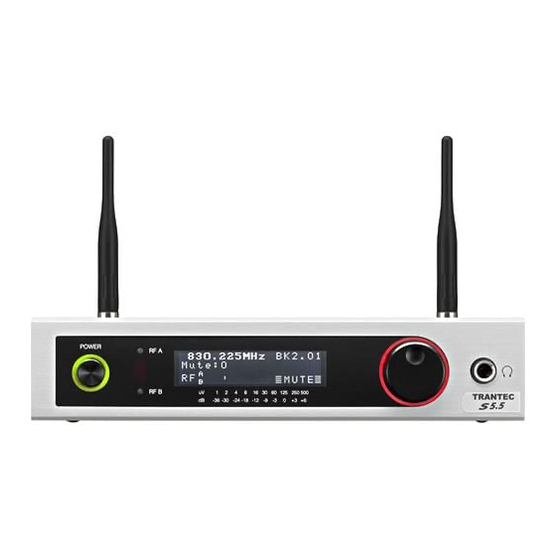
Page 3: Nomenclature And Set-Up
S5.5-RX NOMENCLATURE AND SET-UP Diversity switch A/B indicators Infra-red port Jog wheel Power switch indicator Mute indicator Power On/Off Headphone output Front View DC inlet 1/4” jack output DC strain relief Mic/Line switch USB port XLR output Rear View 1. Attach the supplied antennae (2) to the rear panel TNC antenna connectors as shown in above illustra- tion. -
Page 4: Block Diagram
S5.5-RX BLOCK DIAGRAM Antenna A BP filter RF Amp BP filter BP filter IF Amp BP filter 10.7 Demod BP filter (DF1) (TR1) (DF2) Mixer Mixer Phantom A RSSI A VCO SW RF Amp 45.175MHz (TR5) (TR6) Loop FIlter Phantom B RSSI B 10 MHz Ref (Y3) -
Page 5: Schematic Diagrams
S5.5-RX SCHEMATIC DIAGRAMS 5V_A 5V_A PHANTOM_ENABLE TR31 KTC4075 • MAIN PCB 5V_A 5V_A 5V_A 5V_A TESTPOINT 107DISCRIM TR32 KTC4075 R207 C222 15r_1206 AUDIO_A C206 220p TR35 2SD1622 LL1608-12N LL1608-180N C220 100p 100K FSLU-82n 5V_A LA1225 100p SFE10M7KA00 2SC4399 FH102 C194 BP filter BP filter Antenna B... - Page 6 S5.5-RX • MAIN PCB (Section A) 5V_A 5V_A PHANTOM_ENABLE TR31 KTC4075 5V_A 5V_A 5V_A 5V_A TESTPOINT 107DISCRIM TR32 KTC4075 R207 C222 15r_1206 AUDIO_A C206 220p TR35 2SD1622 LL1608-180N LL1608-12N C220 100K 100p FSLU-82n 5V_A LA1225 100p SFE10M7KA00 2SC4399 FH102 C194 BP filter BP filter Antenna B...
- Page 7 S5.5-RX • MAIN PCB (Section B) IC27D 4011 IC27A IC27B UART_PWM IC27C IR_TX 4011 4011 4011 R253 R255 R254 TESTPOINT IR_TXAND u_OSC1_IN TESTPOINT 10MHz Ref R263 OSC1 A_SWITCH CHAN_A_LED_CL OSC2 u_OSC1_OUT 5V_D CHAN_B_LED_CL 5V_A LCD_CONTRAST 10MHz_SM C200 DISPLAY_RS C232 DISPLAY_RW CHAN_B_LED C198 IC9A...
- Page 8 S5.5-RX • MAIN PCB (Section C) TESTPOINT R135 DEV_METER C127 220n C234 100n R139 R142 HEAD_CLOCK R143 VU_METER UP_DOWN IC13A C129 5V_A C205 R223 MC33078 10u_ELEC 220n 5V_A 100K R140 100K C240 10uF_ELEC R229 R141 BAV99W 5V_A R221 R136 C128 100K C209 2u2_ELEC...
-
Page 9: Led Pcb
S5.5-RX • LED PCB GN D 5V_D RO L_POWRED LC D_CONTRAST DISPLAY_ RED_LED RED_LED DISP LAY_RW DISP_ENAB RD 0 GN D RD 1 RD 2 RD 3 RD 4 RD 5 RD 6 To MAIN PCB ROL_ POWGRN RD 7 5V_D LCD_LE D_A GREEN_LED... -
Page 10: Mounting Diagrams And Parts List
S5.5-RX MOUNTING DIAGRAMS AND PARTS LIST • MAIN PCB • PARTS LIST Type Part Code Description (MAIN PCB) Z3340 PCB ASSY, MAIN S55RX-A11 Z3349 PCB ASSY, MAIN S55RX-B2 Designator Part Code Description Z3341 PCB ASSY, MAIN S55RX-C11 113-40-664-5X CAPACITOR,1608 50V 10NF TAP Z3342 PCB ASSY, MAIN S55RX-D3 113-32-981-6X... - Page 11 S5.5-RX Designator Part Code Description Designator Part Code Description Designator Part Code Description D13-40-032-6X CAPACITOR,U0603C102JNT C142 113-32-976-4X CAPACITOR,MVJ 50VC 2R2M D60 C212 113-32-984-1X CAPACITOR,K 25VC 100M H10 113-40-650-6X CAPACITOR,U0603C681JNT C143 113-40-644-1X CAPACITOR,U0603C221JNT C213 113-32-980-5X CAPACITOR,J 16VC 47M F60 113-40-654-2X CAPACITOR,1608 50V1500PF X7R K C144 113-40-644-1X CAPACITOR,U0603C221JNT...
- Page 12 S5.5-RX Designator Part Code Description Designator Part Code Description Designator Part Code Description 111-31-428-5X IC,LMX2316TM 112-80-393-1X RESISTOR, 22K OHM 5%3/100 112-80-385-8X RESISTOR, 10K OHM 5%3/100 111-06-868-5X IC, NJU4066BM 112-80-337-7X RESISTOR,100 OHM 5%3/100 112-80-409-9X RESISTOR, 100K OHM 5%3/100 111-06-873-5X IC,LA1225M T 112-80-349-8X RESISTOR,330 OHM 5%3/100 DUMMY...
- Page 13 S5.5-RX Designator Part Code Description Designator Part Code Description Designator Part Code Description R149 112-80-361-2X RESISTOR,1K OHM 5%3/100 R219 112-80-385-8X RESISTOR, 10K OHM 5%3/100 TR12 111-01-255-0X TRANSISTOR,KTA2014(GR) R150 112-80-401-9X RESISTOR, 47K OHM 5%3/100 R220 112-80-385-8X RESISTOR, 10K OHM 5%3/100 TR13 111-01-255-0X TRANSISTOR,KTA2014(GR) R151...
-
Page 14: Led Pcb
S5.5-RX • LED PCB • PARTS LIST (Part code : Z3172) (LED PCB) Designator Part Code Description D11-08-042-10 LED, L-934SRC-G(RED) Silk screen drawing (Viewed from parts mounting side) D11-08-042-10 LED, L-934SRC-G(RED) D17-04-005-60 LED, TSUS4300 D11-08-042-10 LED, L-934SRC-G(RED) D11-08-042-10 LED, L-934SRC-G(RED) D11-08-041-80 LED, L-934CGCK(GRN) D11-08-041-80... -
Page 15: Exploded View And Parts List
S5.5-RX EXPLODED VIEW AND PARTS LIST Moving the mouse pointer over the circled number or alphabet, or clicking it on the exploded view pops up indications showing its part number and name. Note that they are not displayed if the cursor is in zoom-in or zoom-out mode. MAIN PCB ASSY. - Page 16 S5.5-RX Moving the mouse pointer over the circled number or alphabet, or clicking it on the exploded view pops up indications showing its part number and name. Note that they are not displayed if the cursor is in zoom-in or zoom-out mode. ·...
Need help?
Do you have a question about the S5.5-RX A1 and is the answer not in the manual?
Questions and answers