Sign In
Upload
Download
Table of Contents
Contents
Add to my manuals
Delete from my manuals
Share
URL of this page:
HTML Link:
Bookmark this page
Add
Manual will be automatically added to "My Manuals"
Print this page
×
Bookmark added
×
Added to my manuals
Manuals
Brands
Bosch Manuals
Security System
NDA-U-PA0
Installation manual
Bosch NDA-U-PA0 Installation Manual
Surveillance cabinet
Hide thumbs
1
2
Table Of Contents
3
4
5
6
7
8
9
10
11
12
13
14
15
16
17
18
19
20
21
22
page
of
22
Go
/
22
Contents
Table of Contents
Bookmarks
Table of Contents
Table of Contents
Important Safety Instructions
Safety Precautions
Important Notices
UL Certification
Bosch Notices
Unpacking
Parts List
Optional Mounting Accessories
Description
Tools Required
Installing the Surveillance Cabinet
Pre-Installation Checklist
Mounting the Surveillance Cabinet
Routing the Wires and Attaching the Connectors
Routing Power through Intermediate Unit
Attaching the Door
Attaching the Pendant Pipe Mount or Pendant Wall Mount
Making Connections in Unit
Connections for Video, Control, Alarm and Relay
Using Fiber Optic Ethernet Media Converter to Transmit Video and Control
Advertisement
Quick Links
1
Installing the Surveillance Cabinet
2
Routing the Wires and Attaching the Connectors
3
Mounting the Surveillance Cabinet
Download this manual
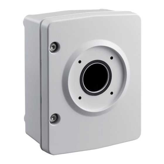
Surveillance Cabinet
NDA-U-PA0 | NDA-U-PA1 | NDA-U-PA2
en
Installation manual
Table of
Contents
Previous
Page
Next
Page
1
2
3
4
5
Advertisement
Table of Contents
Need help?
Do you have a question about the NDA-U-PA0 and is the answer not in the manual?
Ask a question
Questions and answers
Related Manuals for Bosch NDA-U-PA0
Security System Bosch NBN-733 Software Manual
Camera browser interface (111 pages)
Security System Bosch NDN-733 FW5.6 Software Manual
Camera browser interface (111 pages)
Security System Bosch NDA-U-PA1 Installation Manual
Surveillance cabinet (22 pages)
Security System Bosch NDA-U-PA2 Installation Manual
Surveillance cabinet (22 pages)
Security System Bosch ND 200 LSN Installation Manual
(2 pages)
Security System Bosch NBA-7070-PA0 Instruction Manual
Surveillance cabinet (24 pages)
Security System Bosch NBA-7070-PA2 Instruction Manual
Surveillance cabinet (24 pages)
Security System Bosch PRAESENSA PRA-SCL Configuration Manual
Public address and voice alarm system (164 pages)
Security System Bosch ICP-CP508 User Manual
Codepads (8 pages)
Security System Bosch AMAX 2100 Quick Start Manual
(38 pages)
Security System Bosch Solution 2000 Programming
With the icon keypad (12 pages)
Security System Bosch MAP 5000 Series Installation Manual
(90 pages)
Security System Bosch Praesideo Service Manual
Digital public address and emergency sound system (45 pages)
Security System Bosch Security Systems User Manual
(48 pages)
Security System Bosch Security Systems User Manual
(48 pages)
Security System Bosch solution 6000 Installation Manual
(172 pages)
This manual is also suitable for:
Nda-u-pa2
Nda-u-pa1
Table of Contents
Print
Rename the bookmark
Delete bookmark?
Delete from my manuals?
Login
Sign In
OR
Sign in with Facebook
Sign in with Google
Upload manual
Upload from disk
Upload from URL


Need help?
Do you have a question about the NDA-U-PA0 and is the answer not in the manual?
Questions and answers