
Subscribe to Our Youtube Channel
Related Manuals for Synergy E7SE


Summary of Contents for Synergy E7SE
- Page 1 S y n e r g y E 7 S E A s s e m b l y I n s t r u c t i o n s 9 9 9 - 6 0 1 D e s i g n e d b y w w w .
- Page 2 Congratulations on your purchase of the Synergy E7SE radio controlled helicopter kit. The Synergy E7SE was designed and developed by Botos Design & Distribution Inc.. The design of the Synergy E7SE emerged from many years of experience in the hobby including design, research & development, and last but not least as a world class pilot who truly enjoys this wonderful hobby.
-
Page 3: Base Plate Assembly
Base Plate Assembly 101-306 M3 Button Head 103-256 M2.5 Flat Head Cross Recess 101-306 M3x6 Button Head 310-110 Frame Spacer 310-112 Landing Gear Mount 310-103 CF Base Plate Page 1 WWW.SYNERGYRCHELICOPTERS.COM... - Page 4 Main Shaft Bearing Blocks 108-105 10x19x5 Radial Bearing 310-150 Main Shaft Bearing Block E6/7 108-105 10x19x5 Radial Bearing 310-151 Third Main Shaft Bearing Block Important - Keep this orientation in mind for future reference. Make sure bearing block and bearing orientation is correct.
- Page 5 Left Frame Side Assembly 100-306 M3x6 Socket Head 100-308 M3x8 Socket Head 100-306 M3x8 Socket Head 101-306 M3x6 Button Head 100-306 M3x8 Socket Head Page 3 WWW.SYNERGYRCHELICOPTERS.COM...
- Page 6 Tail Servo Install Important! Pivot Ball should be placed at 16mm from center of servo horn Recommended Tail Servo - Futaba BLS256HV or any 760us Tail Servo Tail Servo (Not Included) 100-252 2mm Nylock Nut 107-104 2mm Pivot Ball 100-261 M2.5x10 Socket Head 106-115 Servo Hold Down 100-266 M2.5x6 Socket Head 310-100 Tail Servo Mount...
- Page 7 Sensor Mount Assembly 103-256 M2.5x6 Flat Head 310-104 Sensor Mount Plate 103-256 M2.5x6 Flat Head 310-110 Frame Spacer E6/7 310-105 CF Lower Frame Brace 310-110 Frame Spacer E6/7 Lower Frame Brace Assembly Page 5...
- Page 8 Sensor Mount and Frame Brace Install This hole is for the boom supports. Do not use yet! 101-306 M3x6 Button Head Page 6 WWW.SYNERGYRCHELICOPTERS.COM...
- Page 9 Front Transmission Module 100-351 M3 Nylock Nut Important! - TIghten and secure set screw with loctite. 100-372 M3x12 Set Screw This set screw secures bevel gear pin. 100-354 M3 Washer 108-510 5x10x4 Radial Bearing 320-302 Bevel Gear Top Bearing Block 320-406 2mm Bevel Gear Pin 320-118 18T Front Trans Bevel Gear 320-301 Front Mushroom Gear Bearing Block...
- Page 10 Front Tail Transmission Install Important! Frame is slotted to allow for two different tail gear ratios! 11T(4.9:1) Slide Fore 12T(4.5:1) Slide Aft 101-306 M3x6 Button Head Recommended Tail Ratio - 4.5:1 - Headspeed above 2000 4.9:1 - Headspeed below 1950 Recommended Tail Blades - 4.5:1 - Rail 106-116mm 4.9:1 - Rail 96-106mm...
- Page 11 Right Frame Side Install 100-306 M3x6 Socket Head 101-306 M3x6 Button Head 100-308 M3x8 Socket Head 101-306 M3x6 Button Head 100-306 M3x6 Socket Head Page 9 WWW.SYNERGYRCHELICOPTERS.COM...
- Page 12 Main Frame Alignment Note - Ensure main shaft spins freely within bearings. If main shaft does not spin freely loosen all bolts and ensure frames are square with bearing block. Secure 90.00° all main frame bolts at this time. Page 10 WWW.SYNERGYRCHELICOPTERS.COM...
- Page 13 Servo Horn Assembly IMPORTANT! - Use Red Loctite to secure Pivot Ball to M3 Nut 100-352 M3 Nut 310-107 CF Servo Arm 107-106 Pivot Ball 100-206 M2x6 Socket head Note - It is best to determine servo horn position clostest to 90 degrees before fixing CF servo arm 100-251 M2 Nut to the servo arm wheel.
-
Page 14: Servo Mounting
Servo Mounting Note - All three cyclic servos should be installed at this point in time. At a minimum the elevator servo should be 106-115 Servo Hold Down installed as it may be difficult to install later in the assembly. 100-261 M2.5x10 Socket Head Servo Horn Screw (Not Included) 100-261 M2.5x10 Socket Head... -
Page 15: Landing Gear Assembly
Landing Gear Assembly 610-322 Skid Tube Lock x4 610-324 Landing Gear Strut 610-321 Skid Tube 101-308 M3x8 Button Head 106-966 Skid Tube Plug x4 Complete Landing Gear Page 13 WWW.SYNERGYRCHELICOPTERS.COM... - Page 16 Landing Gear Install 100-312 M3x12 Socket Head Page 14 WWW.SYNERGYRCHELICOPTERS.COM...
- Page 17 Main Boom Clamp Assembly 101-306 M3x6 Button Head 310-108 CF Radio Plate 310-111 Main Boom Clamp E6/7 310-111 Main Boom Clamp E6/7 100-310 M3x10 Socket Head WWW.SYNERGYRCHELICOPTERS.COM Page 15...
- Page 18 Main Boom Clamp Install 100-308 M3x8 Socket Head 100-308 M3x8 Socket Head Page 16 WWW.SYNERGYRCHELICOPTERS.COM...
- Page 19 Brushless Motor Mounting Recommended Motor - Scorpion Ultimate 520kv Available Pinions 305-012 - 12T Helical Pinion 305-013 - 13T Helical Pinion 305-014 - 14T Helical Pinion 305-015 - 15T Helical Pinion Helical Pinion (12T included in kit) Note - Synthetic grease may be used on main gear / pinion in order to reduce heat and improve gear interaction.
- Page 20 Brushless Motor Install 108-615 6x15x5 Radial Bearing(factory installed) 310-152 Motor Shaft Support Bearing Block 710-101 Motor Mount Side Plate 100-312 M3x12 Socket Head Page 18 WWW.SYNERGYRCHELICOPTERS.COM...
- Page 21 ESC Mount Plate Assembly 103-256 M2.5x6 Flat Head Cross Recess 310-102 ESC Mount Plate 310-110 Frame Spacer E6/7 WWW.SYNERGYRCHELICOPTERS.COM Page 19...
- Page 22 ESC Plate Install 100-306 M3x6 Socket Head 100-372 M3x12 Set Screw 100-306 M3x6 Socket Head 100-372 M3x12 Set Screw Page 20 WWW.SYNERGYRCHELICOPTERS.COM...
- Page 23 Female Canopy Mount Install 305-121 Key Chain Canopy Mount, 21mm Female 305-121 Key Chain Canopy Mount, 21mm Female 100-372 M3x12 Set Screw 305-121 Key Chain Canopy Mount, 21mm Female 100-372 M3x12 Set Screw 305-121 Key Chain Canopy Mount, 21mm Female Page 21 WWW.SYNERGYRCHELICOPTERS.COM...
- Page 24 Spur Gear Hub Assembly 320-410 Spur Gear Hub 320-154 54T Spur Gear DO NOT OVER TIGHTEN! Over tightening can crack the Delrin spur gear leading to failure! 103-256 M2.5x6 Type 1Cross Recess Page 22 WWW.SYNERGYRCHELICOPTERS.COM...
-
Page 25: Main Gear Assembly
Main Gear Assembly DO NOT OVER TIGHTEN! Over tightening can crack the Delrin Main gear leading to failure! 101-308 M3x8 Button Head 610-151 Delrin Shim 310-121121T Main Gear 200-407 - Auto Hub Assembly Includes bronze bushings Note - By design the auto hub is symetrical so it can Important - Bronze bushings be used in both orientations. - Page 26 Main Gear to Spur Gear Assembly Align Holes WWW.SYNERGYRCHELICOPTERS.COM Page 24...
- Page 27 Main Gear / Spur Gear Install IMPORTANT! 305-140 E5/7 Main Shaft Ensure boss is facing up when installing the Jesus Bolt Collar! Optional - Use 10mm shim if there is excessive up/down play in the main shaft 100-320A M3x20 Special Bolt 109-110 10mm Main Shaft Shim(optional) 320-411 Jesus Bolt Collar 100-351 Nylock Nut...
-
Page 28: Swash Plate Assembly
Swash Plate Assembly 107-108 Pivot Ball Long x3 107-106 Pivot Ball x4 100-364 M3x4 Set Screw 108-373 3x7x3 Radial Bearing 200-401 Swash Plate Assembly 100-312 M3x12 Socket Head 100-316 M3x16 Socket Head 109-352 3x5x2 Brass Spacer Page 26 WWW.SYNERGYRCHELICOPTERS.COM... -
Page 29: Rotor Head Assembly
520-514 FBL Main Blade Grip 310-201 E7SE Head Block 305-204 Head Axle Pivot 606-803 Head Damper APPLY GREASE! 310-153 E7SE Blade Grip Arm 106-803 8x1mm Shim *Note Thrust Bearing Order Large ID Large OD - Inside Position Small ID Small OD - Outside Position... - Page 30 Swash Follower Arm Assembly Note - Do not tighten 100-323 bolt until the next page. These will pinch and secure the main shaft. 106-301 M3 Shim 108-383 3x8x3 Radial Bearing 305-206 E5 Washout Control Arm 109-352 3x5x2 Brass Spacer 108-383 3x8x3 Radial Bearing 100-323 M3x23 Socket Head 305-207 E5 Ball Link Adapter 100-272 M2.5x12 Set Screw...
- Page 31 Rotor Head Install 100-351 M3 Nylock Nut Pitch Link IMPORTANT! Do not over tighten 100-320A Bolt! 107-100 Ball Link 27.80mm 100-320A M3x20 Special Bolt 107-048 48mm Link Rod IMPORTANT! Do not forget to tighten pinch bolts equally on both sides! 107-100 Ball Link 610-150 Main Shaft Collar M2.5x10 Socket Head...
- Page 32 CCMP Servo Linkage Install CCPM Servo Linkage 107-100 Ball Link 107-043 43mm Link Rod 18.20mm 107-100 Ball Link Page 30 WWW.SYNERGYRCHELICOPTERS.COM...
- Page 33 Tail Box Assembly 101-306 M3x6 Button Head DO NOT OVER TIGHTEN! 108-124 12x18x4 Radial Bearing 100-308 M3x8 Socket Head DO NOT OVER TIGHTEN! 320-220 20T Bevel Mushroom Gear 101-308 M3x8 Button Head 100-351M3 Nylock Nut 320-400 Tail Box 320-405 Tail Box Bearing Spacer 320-412 17mm Bevel Gear Pin 320-409 Tail Bell Crank Mount E7 101-310 M3x10 Button Head...
- Page 34 Tail Pitch Slider Assembly 108-812 8x12x2.5 Radial Bearing 320-320 E7SE Tail Pitch Slider Threaded 506-920 E-Ring 109-813 8x10x3 E7SE Brass Spacer 320-321 E7SE Tail Pitch Plate Threaded 320-319 E7SE Tail Bearing Ring Aluminum IMPORTANT! Use red or green loctite to secure tail pitch plate to tail pitch slider.
- Page 35 Tail Hub Assembly DO NOT OVER TIGHTEN! 108-503 5x10x3 Radial Bearing 100-308 M3x8 Socket Head 515-525 HD Tail Blade Grip 100-354 M3 Washer 106-501 5mm Shim 108-503 5x10x3 Radial Bearing 108-511 5x10x4 Thrust Bearing GREASE THRUST BEARING INNER RACE! Tail Thrust Bearing Note - - Large OD / Large ID - Inside - Small OD/ Small ID - Outside - Shim goes between Thrust...
- Page 36 Tail Box Completion 100-351 M3 Nylock Nut Note - Sizing of ball links is recommended for smooth operation. For best results use Boto-Sizer Tool Part #700-001 106-301 M3 Shim 100-464 - M4x4 Set Screw 100-251 M2 Nut 109-355 3x5x5 Brass Spacer 108-373 3x7x3 Radial 100-330 M3x30 Socket Head 107-104 Pivot Ball 2mm...
- Page 37 Optional - Securing Tail Box Optional but highly recommended, if your tail box departs from your boom because you forgot to pinch the boom clamp, you will wish you took the extra time to do this step! This entire procedure can be done after the torque tube system is installed, just be careful not to drill into your torque tube shaft! Ensure Tail Box is correctly aligned with helicopter.
- Page 38 Optional - Securing Fore Boom Align boom flush with front boom clamp Mark hole through threaded front boom clamp. Do not drill hole at rear boom clamp location! This will weaken boom at high stress point! Drill 3mm hole through marked side of boom(6.5mm from edge of boom) Install M3x6 Button Head Bolt with blue loctite to secure boom 101-306 M3x6 Button Head Tail Boom...
-
Page 39: Tail Control Rod Assembly
Tail Control Rod Assembly Note - Lightly sand carbon tail control rod prior to securing with JB Weld! 315-111 E7 Tail Control Rod 728mm Note - Tail push rod ends will slide through tail control guides. 106-965 Tail Push Rod Sleeve (Teflon) 305-311 Tail Push Rod End IMPORTANT! - Tail Control Rod End must be secured with high quality glue such as JB Weld. -
Page 40: Torque Tube Assembly
Torque Tube Assembly Note - Install bearings on torque tube shaft before installing torque tube ends. Bearings will not slide over ends. 108-814 8x14x4 Radial Bearing Apply RED Loctite to secure bearing to Torque Tube. Do not apply loctite to plastic 320-503 Torque Tube Bearing Housing 320-504 O-Ring 100-210 M2x10 Socket Head... - Page 41 Boom Support Assembly Sand Ends lightly before 115-119 Boom Support End applying glue! Top - attaches to boom clamp 115-119 Boom Support End 315-117 E7 Boom Support 580mm Notes - 1. Use Epoxy or JBWeld 2. Ensure ends are in alignment while glue sets 109-345 3x4x5 Brass Spacer Bottom - attaches to frames Sand Ends Lightly Before...
- Page 42 Tail Boom Assembly Note - Use silicone based grease for installation of torque tube assembly into the tail boom. 610-128 Boom Support Clamp, Lite 115-114 Tail Control Guide 100-312 M3x12 Socket Head Torque Tube Assembly (page 38) Tail Control Rod Assembly (page 37) 315-140 E7 Boom 812mm 100-312 M3x12 Socket Head Note - Tail Boom will remain flush with front boom mount.
- Page 43 Tail Box Install 100-308 M3x8 Socket Head IMPORTANT! Do not over tighten bolts! 101-308 M3x8 Button Head IMPORTANT! Do not over tighten bolts! WWW.SYNERGYRCHELICOPTERS.COM Page 41...
- Page 44 Boom Support Install 101-412 M4x12 Button Head 100-354 M3 Washer 100-316 M3x16 Socket Head WWW.SYNERGYRCHELICOPTERS.COM Page 42...
- Page 45 Main Blade Install 696-716mm Main Blades M5x35 Socket Head Blade Spacers (Not Included) Blade spacers are usually included by rotor blade manufacturer M5 Nylock Nut WWW.SYNERGYRCHELICOPTERS.COM Page 43...
- Page 46 Tail Blade Install IMPORTANT! Select correct tail blade size per Head Speed RPM! 2000 and up - 96-106mm Tail Blades 1950 and lower - 106-116mm Tail Blades Note - Counter clockwise rotating tail. Install tail blades as illustrated. 100-316 M3x16 Socket Head 100-351 M3 Nylock Nut 106-804 Tail Blade Spacers WWW.SYNERGYRCHELICOPTERS.COM...
-
Page 47: Canopy Assembly
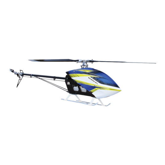
Canopy Assembly Note - Canopy holes may need enlarged to approximately 8-9mm in order to correctly install the canopy rubber grommet. 310-405 E7SE Canopy 305-126 Key Chain Canopy Grommet 305-125 Key Chain Canopy Mount, Male Page 45 WWW.SYNERGYRCHELICOPTERS.COM... - Page 48 Synergy E7SE - Completed! 365 mm 1330 mm WWW.SYNERGYRCHELICOPTERS.COM Page 46...
- Page 49 Synergy E7SE - Top View 1549.500 with Rail 696 Blades Landing Gear Width 214.25mm Bolt to Bolt 157.500 WWW.SYNERGYRCHELICOPTERS.COM Page 47...
Need help?
Do you have a question about the E7SE and is the answer not in the manual?
Questions and answers