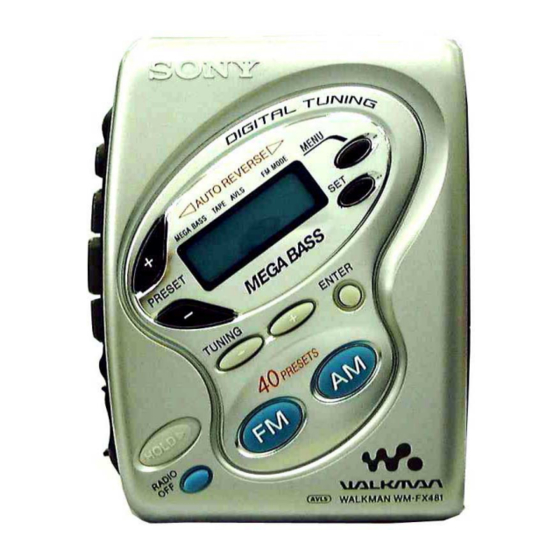
Sony WM-FX481 Service Manual
Radio
Hide thumbs
Also See for WM-FX481:
- Operating instructions (2 pages) ,
- Specifications (2 pages) ,
- Service manual (2 pages)
Table of Contents
Advertisement
QQ
3 7 63 1515 0
SERVICE MANUAL
Ver 1.0 2001.04
TE
L 13942296513
www
.
Sony Corporation
9-873-125-11
2001D0200-1
Personal Audio Company
© 2001.4
Shinagawa Tec Service Production Group
http://www.xiaoyu163.com
x
ao
u163
y
i
http://www.xiaoyu163.com
WM-FX481
2 9
8
Model Name Using Similar Mechanism
MD Mechanism Type
SPECIFICATIONS
Q Q
3
6 7
1 3
1 5
RADIO CASSETTE PLAYER
co
.
9 4
2 8
E Model
Chinese Model
NEW
MF-WMFX481-114 (5E, 6E, 9E)
MF-WMFX467-114 (CH)
• Abbreviation
CH
: Chinese
9E
: No Indication of country of origin
0 5
8
2 9
9 4
2 8
5E, 6E : Indication of country of origin
m
9 9
9 9
Advertisement
Table of Contents

Related Manuals for Sony WM-FX481


Summary of Contents for Sony WM-FX481
- Page 1 WM-FX481 3 7 63 1515 0 SERVICE MANUAL E Model Chinese Model Ver 1.0 2001.04 Model Name Using Similar Mechanism MF-WMFX481-114 (5E, 6E, 9E) MD Mechanism Type MF-WMFX467-114 (CH) • Abbreviation : Chinese SPECIFICATIONS : No Indication of country of origin...
-
Page 2: Table Of Contents
WM-FX481 3 7 63 1515 0 TABLE OF CONTENTS Specifications ................1 Flexible Circuit Board Repairing • Keep the temperature of the soldering iron around 270°C during 1. GENERAL repairing............... 2 • Do not touch the soldering iron on the same conductor of the circuit board (within 3 times). -
Page 3: Disassembly
WM-FX481 SECTION 2 3 7 63 1515 0 DISASSEMBLY The equipment can be removed using the following procedure. Mechanism deck Belt, Capstan/reel motor (M601) Cabinet (center) sub ASSY Main board Magnetic head (playback) (HP601) Cabinet (front) Cassette holder Note : Follow the disassembly procedure in the numerical order given. -
Page 4: Mechanism Deck
WM-FX481 3 7 63 1515 0 2-3. MECHANISM DECK Mechanism deck 1 Claws Cabinet (center) sub ASSY L 13942296513 2-4. BELT, CAPSTAN/REEL MOTOR (M601), MAGNETIC HEAD (PLAYBACK) (HP601) 3 Screws (M1.4) 5 Screws (M1.4) 4 Capstan/reel motor Mechanism deck (M601) •... -
Page 5: Cassette Holder
WM-FX481 3 7 63 1515 0 2-5. CASSETTE HOLDER 2 Move the hinge away from projection Hinge Projection Projection 3 Move the hinge away from projection Hinge Projection Cabinet (center) sub ASSY Projection Hinge Hinge 4 Spring (torsion) Cassette holder... -
Page 6: Adjustments
WM-FX481 SECTION 3 ADJUSTMENTS 3 7 63 1515 0 3-1. MECHANICAL ADJUSTMENTS 3-2. ELECTRICAL ADJUSTMENTS PRECAUTION PRECAUTION 1. Clean the following parts with a denatured-alcohol-moistened • Supplied voltage : 2.5V. swab : • Switch and control position (MENU display) - Page 7 WM-FX481 3 7 63 1515 0 • Repeat the procedures in each adjustment several times, and the TUNER SECTION 0 dB = 1µV frequency coverage and tracking adjustments should be finally AM Section done by the trimmer capacitors. BAND : AM no mark : 10kHz step <...
- Page 8 WM-FX481 3 7 63 1515 0 FM VCO Adjustment Procedure : FM RF signal generator 0.01 µ F (FM IN) Carrier frequency : 98MHz 33.75kHz frequency deviation by 1kHz signal. Modulation : L = -R Output level : as low as possible...
-
Page 9: Diagrams
WM-FX481 SECTION 4 DIAGRAMS 3 7 6 3 1 5 1 5 0 4-1. EXPLANATION OF IC TERMINALS • Abbreviation : Chinese IC702 LC72348W-CFX1721(5E, 6E) SYSTEM CONTROL : No Indication of country of origin IC702 LC72348W-CFX1726(9E, CH) SYSTEM CONTROL 5E, 6E : Indication of country of origin Pin No. -
Page 10: Block Diagram
WM-FX481 4-2. BLOCK DIAGRAMS 3 7 6 3 1 5 1 5 0 1 3 9 4 2 2 9 6 5 1 3 w w w u 1 6 3 • Abbreviation • Signal path. : FM : Chinese... -
Page 11: Schematic Diagram
WM-FX481 4-3. SCHEMATIC DIAGRAM 3 7 6 3 1 5 1 5 0 Refer to page 14 for Notes. Refer to page 14 for Waveforms. Refer to page 14 for IC Block Diagrams. 1 3 9 4 2 2 9 6 5 1 3... -
Page 12: Printed Wiring Boards - Main Section (Side A)
WM-FX481 3 7 6 3 1 5 1 5 0 4-4. PRINTED WIRING BOARDS – MAIN SECTION (SIDE A) – Semiconductor Location Ref. No. Location MAIN BOARD (SIDE A) IC301 IC701 IC702 Q301 Q501 Q502 Q701 1 3 9 4 2 2 9 6 5 1 3... -
Page 13: Printed Wiring Boards - Main Section (Side B)
WM-FX481 4-5. PRINTED WIRING BOARDS – MAIN SECTION (SIDE B) – 3 7 6 3 1 5 1 5 0 DRY BATTERY SIZE "AA" Semiconductor (IEC DESIGNATION R6) Location 2PCS, 3V MAIN BOARD (SIDE B) Ref. No. Location D404... - Page 14 WM-FX481 3 7 6 3 1 5 1 5 0 • IC BLOCK DIAGRAMS Note on Schematic Diagram: MAIN SECTION Waveforms IC1 CXA1960Q • All capacitors are in µF unless otherwise noted. pF: µµF 50 WV or less are not indicated except for electrolytics 22 21 and tantalums.
-
Page 15: Exploded Views
WM-FX481 SECTION 5 EXPLODED VIEWS 3 7 63 1515 0 NOTE : • Hardware (# mark) list and accessories and packing • -XX, -X mean standardized parts, so they materials are given in the last of this parts list. -
Page 16: Mechanism Deck Section
WM-FX481 3 7 63 1515 0 5-2. MECHANISM DECK SECTION MF-WMFX467-114 : CH MF-WMFX281-114 : 5E, 6E, 9E supplied supplied not supplied supplied L 13942296513 supplied supplied supplied M601 HP601 Ref. No. Part No. Description Remark Ref. No. Part No. -
Page 17: Electrical Parts List
WM-FX481 SECTION 6 MAIN ELECTRICAL PARTS LIST 3 7 63 1515 0 NOTE : • Due to standardization, replacements in the • Items marked “ * ”are not stocked since they When indicating parts by reference num- parts list may be different from the parts are seldom required for routine service. - Page 18 WM-FX481 MAIN 3 7 63 1515 0 Ref. No. Part No. Description Remark Ref. No. Part No. Description Remark C602 1-115-467-11 CERAMIC CHIP 0.22uF <COIL> C603 1-165-176-11 CERAMIC CHIP 0.047uF C604 1-165-176-11 CERAMIC CHIP 0.047uF 1-412-967-31 INDUCTOR 0.1uH C605 1-165-176-11 CERAMIC CHIP 0.047uF...
- Page 19 WM-FX481 MAIN 3 7 63 1515 0 Ref. No. Part No. Description Remark Ref. No. Part No. Description Remark R205 1-216-815-11 METAL CHIP 1/16W <VIBRATOR> R206 1-216-831-11 METAL CHIP 6.8K 1/16W X701 1-579-615-11 VIBRATOR, CRYSTAL (75kHz) R207 1-216-864-11 METAL CHIP...
- Page 20 WM-FX481 3 7 63 1515 0 REVISION HISTORY Clicking the version allows you to jump to the revised page. Also, clicking the version at the upper right on the revised page allows you to jump to the next revised page.
Need help?
Do you have a question about the WM-FX481 and is the answer not in the manual?
Questions and answers