
Related Manuals for RELACART UR-220S

Summary of Contents for RELACART UR-220S
- Page 1 UR-220S / 220D Series Professional UHF Wireless Microphones Installation and Operation...
-
Page 2: Table Of Contents
Receiver Controls and Functions… … … … … … … … … … … … … … … … … … … … … … … …P5 UR-220S Front panel… … … … … … … … … … … … … … … … … … … … … … … … … … … … … …P5 UR-220S Rear panel…... -
Page 3: Introduction
Introduction Receiver Installation and Connections ①EIA-standard metal 1/2 - rack receiver chassis, antenna diversity. Installation: ②The Handheld Transmitter offers durable, ergonomic metal bodies, soft-touch controls. ③Bright and easy-to-read LCD display shows RF/AF, diversity strengths; transmitter battery level; ①For better operation the receiver should be at least 3ft. 1m above the ground and at least 3ft. meanwhile, can set up selective channel, frequency, mute and other working status. -
Page 4: Receiver Controls And Functions
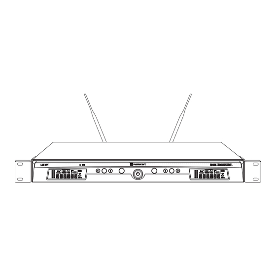
Receiver Controls and Functions Figure A: UR-220S Receiver Front Panel Figure B: UR-220S Receiver Rear Panel ①Power Switch:Press power switch in 3 seconds and the receiver readouts will light. ①Antenna Input Jack: BNC type antenna connector for tuner ”B”, attached the antenna directly. - Page 5 Figure C: UR-220D Receiver Front Panel ⑤A Channel SET Button: Use in conjunction with the Up / Down arrow buttons to step through menus, choose operating frequency and select receiver function options. ⑥A Channel Infrared Data Transfer Button (SYNC): Press this button to transmit A channel data from receiver to transmitter.
-
Page 6: Transmitter Controls And Functions
Transmitter Controls and Functions Handheld Microphone Figure D: UR-220D Receiver Rear Panel 7 8 9 ①AC Power Input: IEC type connector for 100-240V, 50/60Hz without user adjustment. ②Antenna Input Jack: BNC type antenna connector for tuner ”B”, attached the antenna directly. ③B Channel Volume Button: To adjust the volume. -
Page 7: Bodypack Transmitter
Transmitter Battery Installation: Body-pack Transmitter ①Antenna ②Power Button ③Mute Button: When the transmitter is muted, it products RF with no audio signal modulation; when the transmitter is un-muted, it products both RF and audio. ④Audio Input Jack: To connect 4-pin mini-XLR connector. ⑤LCD Window: Liquid crystal display indicates operational frequency, channel and battery condition. -
Page 8: System Setup
System Setup Receiver Setup ①Turn down the AF level of the associated mixer or amplifier, and make sure that any UR transmitters are turned off. ②Turn on the receiver, the LCD displays the preset data. ③To change the frequency by manual or “AFS” (Auto Frequency Scan). a, Touch button once to select a new frequency. -
Page 9: Transmitter Setup
A, Turn on one transmitter, to let the transmitter IR receiving window face to the receiver IR data transfer window, then press A Channel's “SYNC” button, the transmitter will receive the frequency / channel Transmitter Setup dada from A Channel, simultaneously the LCD displays the same frequency / channel as the receive A Channel. -
Page 10: Specifications
RF Power Output: 90mW Weight: 1.9KG (UR-220S); 4KG (UR-220D) Battery: AA X 2 Dimension: 210(W)X 43(H) X 206(D) – UR-220S / 421(W) X 43(H) X 206(D) – UR-220D Current Consumption: 90mA, typical Output Connector: XLR balanced & 6.3 φphone jack unbalanced... - Page 13 USA acceptable band ( FCC compliance ): 618.500 MHz – 633.500 MHz Canada acceptable band ( IC compliance ): 678.500 MHz – 693.500 MHz Europe acceptable band ( CE compliance): 850.000 MHz – 865.000 MHz FCC NOTE: This device complies with Part 15 of the FCC Rules. Operation is subject to the following two conditions:(1)this device may not cause harmful interference, and (2) this device must accept any interference received, including interference that may cause undesired operation.
Need help?
Do you have a question about the UR-220S and is the answer not in the manual?
Questions and answers