Advertisement
Quick Links
Dual-Wire Workstation Continuous Monitor
Installation, Operation, and Maintenance
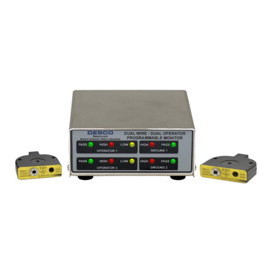
Figure 1. Desco
19665
Dual Wire - Dual Operator
Programmable Monitor
Description
Continuous monitors pay for themselves, by improving quality,
productivity, and eliminating daily wrist strap testing and test
result logging. Per ESD-S1.1 paragraph 6.1.3 Frequency of
Functional Testing, "The wrist strap system should be tested
daily to ensure proper electrical value. Daily testing may be
omitted if constant monitoring is used."
Per ESD Handbook TR20.20 paragraph 5.3.2.4.4, "Typical
test programs recommend that wrist straps that are used daily
should be tested daily. However, if the products that are being
produced are of such value that knowledge of a continuous,
reliable ground is needed, and then continuous monitoring
should be considered or even required."
The Desco Dual Wire - Dual Operator Programmable Monitor
can maintain two work surfaces and two operators at ground
potential to virtually eliminate the risk of ESD damage. The
highly visible LED display and audible alarm makes it easy to
monitor the status of the work surfaces and operators. The
Dual-Wire Dual-Operator Programmable Monitor uses Desco's
patented* dual resistive loop technology. No other method is as
direct and reliable. Both work surfaces, and individual operator
resistance limits, can be programmed and re-configured
as required. If the ground potential of either work surface
or operator is lost the, monitor immediately alarms (both
audible and visual). The monitor is unaffected by capacitance
variations associated with personnel and environmental
conditions.
The Dual Wire - Dual Operator Programmable Monitor
features:
• Monitoring of two operators independently.
• Monitoring of two ground connections (work surfaces)
independently.
• Fully independent alarming conditions: audible and visual.
• Independent LED status lights for each operator and each
ground connection (work surface.)
• Two independent operator wrist strap ground point remotes
with 10' cables.
NOTE: Use dual-wire wrist straps with this monitor.
*U.S. Patents 6,052,053 and 6,205,408
DESCO
EAST - One Colgate Way, Canton, MA 02021-1407 • (781) 821-8370 • Fax (781) 575-0172 • Web Site: Desco.com
TB-3019 August 2010 Page 1 of 4
TECHNICAL BULLETIN TB-3019
DESCO WEST - 3651 Walnut Avenue, Chino, CA 91710 • (909) 627-8178 • Fax (909) 627-7449
TERMINAL
SCREWS (DO NOT
OVER TIGHTEN)
POWER CONNECTION
12VDC CENTER POSITIVE
PLUG IN OPERATOR 1 CABLE HERE
(WHITE CABLE)
PLUG IN OPERATOR 2 CABLE HERE
(BLACK CABLE)
Figure 2. Dual Wire - Dual Operator Programmable Monitor
rear view
Packaging
1 Dual Wire - Dual Operator Programmable Monitor
2 Operator Remotes
2 Operator Remote Cables (1 Black, 1 White)
1 Power Adapter
2 Mat Monitor Cables (1 Black, 1 White)
2 6' Mat Ground Cords with Additional Ring Terminals (Green
and Yellow)
1 10' Monitor Ground Cord (Green and Yellow)
Installation
A. Determine the mounting location of the monitor. The front
panel should be visible to a supervisor.
B. Determine the mounting location of the operator remotes.
The white remote is for operator #1 and the black remote is
for operator #2. Make sure that each remote is located so
that the remote leads reach the monitor but are convenient
for the operator.
C. Attach the operator remotes to the bench or other surface
using the provided screws. (See Figure 7).
D. Attach the tinned wire ends of the mat wires to the
appropriate screw terminal connection on the rear of the
unit. (See Figure 2). The white wire is for operator #1 and
the black wire is for operator #2.
E. If not already done, attach the work surface to workstation
common point ground using the pictured ground wires. For
mats, attach the grounding point snaps at the ends of the
ground monitor cords to the grounding point snaps on the
work surface. These ground monitor cords are used for
sensing whether or not the unit is properly grounded. Refer
to figure 3 for snap-plate fitting diagram and for laminates or
ther hard surfaces with a buried conductive layer.
F. Attach the tinned wire end of the black ground-reference
wire to the center position of the screw terminal block on
the rear of the unit. Attach the ring terminal end to an
alternate ground point. It is important that this ground wire is
attached to a separate ground point other than the work
surface ground cords from the previous step to ensure
proper independent monitoring. The faceplate screw of a
grounded AC wall outlet may provide a convenient
connection point.
Made in America
VOLUME ADJUSTMENT
(COUNTER CLOCKWISE
TO INCREASE VOLUME
DATA PORT RJ45
CONNECT TO BLACK 10mm CORD TO
10mm SNAP ON WORK SURFACE 1
CONNECT TO EARTH GROUND
CONNECT TO WHITE 10mm CORD TO
10mm SNAP ON WORK SURFACE 1
© 2010 DESCO INDUSTRIES INC.
Employee Owned
Advertisement

Subscribe to Our Youtube Channel
Related Manuals for Desco 19665


Summary of Contents for Desco 19665
- Page 1 The white remote is for operator #1 and the black remote is The Desco Dual Wire - Dual Operator Programmable Monitor for operator #2. Make sure that each remote is located so can maintain two work surfaces and two operators at ground that the remote leads reach the monitor but are convenient potential to virtually eliminate the risk of ESD damage.
- Page 2 AC outlet and plug the power adapter into the outlet. Make sure the voltage and frequency match those listed on the AC adapter. The monitor should now be powered. DESCO WEST - 3651 Walnut Avenue, Chino, CA 91710 • (909) 627-8178 • Fax (909) 627-7449 DESCO EAST - One Colgate Way, Canton, MA 02021-1407 • (781) 821-8370 • Fax (781) 575-0172 • Web Site: Desco.com © 2010 DESCO INDUSTRIES INC. TB-3019 Page 2 of 4 Employee Owned...
- Page 3 Dual Wire - Dual Operator ft. (2 km) Monitor. See EMIT TB-6542 for instructions. • Maximum relative humidity of 80% up to 88°F (31°C) decreasing linearly to 50% @104°F (40°C) • Pollution degree 2 per IEC 644 • Temperature range of 41°F (5°C) to 104°F (40°C) DESCO WEST - 3651 Walnut Avenue, Chino, CA 91710 • (909) 627-8178 • Fax (909) 627-7449 DESCO EAST - One Colgate Way, Canton, MA 02021-1407 • (781) 821-8370 • Fax (781) 575-0172 • Web Site: Desco.com © 2010 DESCO INDUSTRIES INC. TB-3019 Page 3 of 4 Employee Owned...
- Page 4 Limit of Liability In no event will Desco or any seller be responsible or liable for any injury, loss or damage, direct or consequential, arising out of the use of or the inability to use the product. Before using, users...
Need help?
Do you have a question about the 19665 and is the answer not in the manual?
Questions and answers