Table of Contents
Advertisement
Advertisement
Table of Contents

Related Manuals for Abloy DA461


Summary of Contents for Abloy DA461
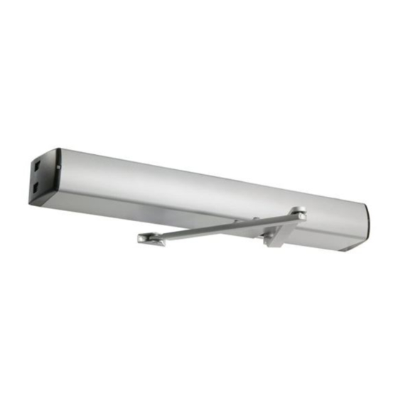
- Page 1 ABLOY ® DA461 SWING DOOR OPERATOR Installation and commissioning manual...
- Page 2 Ensure that entrapment between door and the surroundings is avoided. Ensure that the operator is suited for installation. Check temperature, humidity, door weights, etc. restriction in line with specifi cations applicable in the manual or other Abloy® Oy material. Note! Instructions, design specifi...
-
Page 3: Table Of Contents
CONTENTS REVISION ..........................4 CONTENT OF DELIVERY ......................5 GENERAL INFORMATION ....................... 6 OPERATION ........................... 7 MAIN SWITCH AND MODE SWITCH ..................7 DOOR WEIGHT ........................8 INSTALLATION ........................9 7.1 Installing the mounting plate DA104 ................10 7.2 Assembly of the operator and standard arm DA147, DA148 to the closing side ... 11 7.3 Assembly of the operator and sliding arm DA149 to the closing side ...... -
Page 4: Revision
REVISION Following pages have been revised: Page Revision Safetysensor-unit added into connections. 17-18 Settings updated. Added a note about safety sensors. 20-25 All connections drawings updated. Safety sensor diagnistics added. Safetysensor-unit info added. As at 21.05.2015. -
Page 5: Content Of Delivery
CONTENT OF DELIVERY DA461 Swing door operator - screws 6 pcs M6x14 - adapter - spanner wrench DA104 Mounting plate - screws 6 pcs 5,5x32 - ordered separately DA147 Standard arm - screws 2 pcs 5,5x32 and 1 pcs M8x20 + M8x30... -
Page 6: General Information
GENERAL INFORMATION Technical data Measures • 721 (L) x 85 (H) x 107 (W) mm • Weight 9 kg • Supply voltage 100/230 VAC (±10 %) 50...60 Hz • Rated output 120 W • Enclosure class IP20 Temperature range • Storage -20...50 °C (in dry premises) •... -
Page 7: Operation
If the opening cycle of the door operator is interrupted, the clutch mechanism will disengage, the ABLOY ® DA461 will try to open the door four times, stopping for one second before each attempt. After fourth attempt the clutch will release, and the door will close via the on board door closer. -
Page 8: Door Weight
DOOR WEIGHT Standard arm 100 110 120 130 140 150 Door width [cm] Sliding arm 100 110 120 130 140 150 Door width [cm]... -
Page 9: Installation
INSTALLATION Tools required - Drill - Set of ball ended allen wrenches - # 2 Phillips head screwdriver - Flat blade screwdrivers, 2 pcs Steps of installation - Preparing installation - Installing the mounting plate - Mounting the operator and the arm - Connecting the operator to mains - Commissioning - Testing... -
Page 10: Installing The Mounting Plate Da104
Installing the mounting plate DA104 The operator is installed on the transom, with the main switch located towards the hinge side of the door. Use the mounting plate DA104 with the door operator ensuring the installation base is level. Securely fi x the mounting plate to the transom. -
Page 11: Assembly Of The Operator And Standard Arm Da147, Da148 To The Closing Side
Assembly of the operator and standard arm DA147, DA148 to the closing side DA104 Mounting of the operator: M6x14 and washer Min 21 320* * If you need closing force according to EN1154 class 6, use measurement 300 mm. Length of Mounting of extension piece the arm... -
Page 12: Assembly Of The Operator And Sliding Arm Da149 To The Closing Side
Assembly of the operator and sliding arm DA149 to the closing side DA104 Mounting of the operator: M6x14 and washer Min 38 Frame Arm distance Minimum door Length of Mounting depth L/mm width M/mm extension piece of the arm < 50 No extension piece M8x20 + washer 50-100... -
Page 13: Assembly Of The Operator And Sliding Arm Da149 To The Opening Side
Assembly of the operator and sliding arm DA149 to the opening side DA104 Mounting of the operator: M6x14 and washer Min 14 Max 20 Frame Arm distance Minimum door Length of Mounting depth L/mm width M/mm extension piece of the arm <... -
Page 14: Removing Of The Position Sensor
Removing of the position sensor Removing of the position sensor The position sensor must be removed, if the clutch or closing force need adjustment. This prevents possible damage of the sensor during adjustment. Fixing screw for position sensor Position sensor removed Door Closer Adjustments Closing speeds Closing speed... - Page 15 Closing force adjustment Open the door fully and observe the closing function assuming that the door closes as is required, check the closing function from approximately 15° from the door’s closed position ensuring that there is suffi cient power to close the door fully. Before adjusting the force of the door closer it is sensible to try and obtain a satisfactory closing action utilising the closing and latching speed.
-
Page 16: Internal Connections
When not mains operated, or for back-up supply, the external 24VDC (±15 %) supply (min 5A) can be connected to X1 connectors 2 and 3. Connect + from DC supply back-up to X1 connector 2 and GND to connector 3. No battery charging or maintenance is provided by DA461. -
Page 17: Commissioning
COMMISSIONING 1 Check the free movement of the door. 2 Turn mode switch to MAN. The mode switch is located in the head panel. 3 Plug in the mains and turn the switch on. The main switch is located in the head panel. 4 Choose the type of the arm. - Page 18 9 Opening speed and hold open time Adjust the opening speed. A slow door is a safe door. The door speed should be set to allow SPEED unhindered access but as slow as is possible.. Säädä aukioloaika (0...60 s) HOLD OPEN -säätimestä. Kun säädin käännetään alueelle ”seq”, joka toinen impulssi avaa oven ja joka toinen sulkee sen.
-
Page 19: Safe Door
We recommend that safety sensors are fi tted to all applications, particularly on the driven side, opening face in the case of a DA461. Higher speeds are only achievable when full safety is specifi ed. -
Page 20: External Connections
When the ABLOY DA461 is fi tted to a Fire Resisting door set, the door operator MUST be interfaced with the ® Fire Detection system. Local requirements will vary, but the door must close in the event of activation in line with current European regulations. -
Page 21: Connection Examples
12 CONNECTION EXAMPLES Safety sensor DA004 and DA005 green brown blue, yellow, pink violet white 1 2 3 4... -
Page 22: Da061 Microwave Motion Sensor
12.2 DA061 Microwave motion sensor yellow white brown green 12.3 DA063 Microwave motion sensor white pink yellow blue brown green... -
Page 23: Da033 Elbow Switch
12.4 DA033 Elbow switch 12.5 DA039 and DA049 rotary switch blue black... -
Page 24: Electric Locks El402, El404, El502
12.6 Electric locks EL402, EL404 and EL502 black blue green NOTE! Not to be installed in doors with seal force. Bolt and trigger bolt have to be lubricated when lock is installed and when necessary. 12.7 Motor locks EL490 ja EL590 gray blue green... -
Page 25: Fire Door System
12.8 Fire door system Motor lock gray EL490/EL590 blue green white Adjust the lock delay to minimum OPERATION: When the fi re detection system reacts, it’s relay switches on. Then the GND (-) is disconnected from the operator’s control unit (connector 2). The operator doesn’t open the door from impulse but it can be opened manually. -
Page 26: Self Diagnostics
13 SELF DIAGNOSTICS (CONTROL UNIT) Fault codes - detect malfunctions - to ensure safe operation where possible during malfunction - to restore the operator to its required status If the door operator is unrecoverable it will revert to manual operation only. Both LED’s will blink. -
Page 27: Maintenance
B fl ash C fl ash D fl ash 14 MAINTENANCE Door operators require periodic maintenance. Only trained personel are equiped to work on ABLOY DA products. ® Door leaf is moving sensitively and locking works well. Regular annual services are made: - Under 100 openings per day;... -
Page 28: Adjusting The Clearance Of The Electromagnetic Clutch
28). The clearance should be 0,3 mm. Re-adjust the clutch if needed. Incorrect clearance causes, clutch drag or clutch slip, preventing the correct operation of the door operator. ABLOY ® Holding screws Remove the position sensor before adjusting the clutch (see p.14). -
Page 29: Spare Parts
15 SPARE PARTS Head panel Motor and clutch 810174 812251 Safetysensor-unit Position sensor 5742362 Control unit 811339 811990 Transformer 811377 Mode switch 811456 Door closer 811702 closing side 811753 opening side Adapter 410351 aluminium 410352 white Main switch 807437 DA147/100000 A DA147/600000 V DA147/800000 E DA148/100000 A... - Page 32 Abloy Oy and in the air – in all circumstances. Wahlforssinkatu 20 P.O. Box 108 ASSA ABLOY is the global leader in door opening solutions, dedicated to satisfying FI-80101 Joensuu | Finland end-user needs for security, safety and Tel. +358 20 599 2501 convenience.
Need help?
Do you have a question about the DA461 and is the answer not in the manual?
Questions and answers