Abloy DA460 Installation And Commissioning Manual
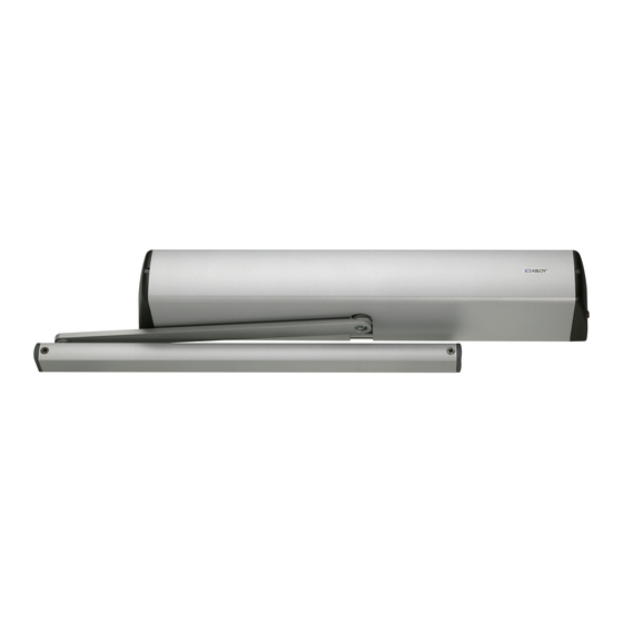
Swing door operator
Hide thumbs
Also See for DA460:
- Installation and commissioning manual (33 pages) ,
- Installation and commissioning manual (33 pages)
Table of Contents
Advertisement
Advertisement
Table of Contents

Related Manuals for Abloy DA460


Summary of Contents for Abloy DA460
- Page 1 ABLOY ® DA460 SWING DOOR OPERATOR Installation and commissioning manual...
-
Page 2: Approvals
Ensure that entrapment between door and the surroundings is avoided. Ensure that the operator is suited for installation. Check temperature, humidity, door weights, etc. restriction in line with specifi cations applicable in the manual or other Abloy® Oy material. Note! Instructions, design specifi... -
Page 3: Table Of Contents
CONTENTS Approvals ..........................2 Revision ..........................4 Content of delivery ......................5 General information ......................6 Operation ........................... 7 Main switch and mode switch ....................7 Door weight ........................8 Installation ......................... 9 Internal connections ......................14 Commissioning ......................... 15 A safe door ........................ -
Page 4: Revision
REVISION Following pages have been revised: Page Revision Safetysensor-unit added into connections. 15-16 Settings updated. Added a note about safety sensors. 19-26 All connections drawings updated. Safety sensor diagnistics added. Safetysensor-unit info added. As at 22.05.2015. -
Page 5: Content Of Delivery
CONTENT OF DELIVERY DA460 Swing door operator - screws 4 pcs M8x22 DA103 Mounting plate - screws 6 pcs 5,5x32 DA147 Standard arm - screws 2 pcs 5,5x32 and 1 pcs M8x30 DA148 Extended arm - screws 2 pcs 5,5x32 and... -
Page 6: General Information
GENERAL INFORMATION Technical data Measures • 595 (L) x 85 (H) x 107 (W) mm • Weight 6,5 kg • Supply voltage 90-264 VAC, 47-63 Hz • Rated output 70 W • Enclosure class IP20 Temperature range • Storage -30...+85°C (in dry premises) •... -
Page 7: Operation
OPERATION DA460 is an electromechanical swing door operator for heavy use. The door operator includes new ABLOY ® free swing function: when using the door manually it operates lightly without motor’s resistance and the door can be left in open position when required. It can be used on both single and double, internal and external, fi re and emergency exit doors. -
Page 8: Door Weight
DOOR WEIGHT Standard arm Door width [cm] Sliding arm Door width [cm]... -
Page 9: Installation
INSTALLATION Tools required Drill Set of ball ended allen wrenches # 2 Phillips head screwdriver Flat blade screwdrivers, 2 pcs Steps of installation - Preparing installation - Installing the mounting plate - Mounting the operator and the arm - Connecting the operator to mains - Commissioning - Testing - Connecting impulse devices... - Page 10 Installing the mounting plate Operator is to be installed on the transom, with the main switch located towards the hinge. Use the mounting plate DA103 with the door operator ensuring the installation base is level and securely fi xed to a fl at surface. Minimum requirement for wall profi le is 5 mm (steel). Installation measurements for the standard arms DA147, DA148 and sliding arm DA149 to closing side.
- Page 11 Assembly of the operator and the standard arm to the closing side Mounting of the operator M8x22 and washer Hinge line Mounting of the arm to the operator M8x30 and washer Y (mm) Length of extension piece No extension piece 10 mm (DA150/01) 20 mm (DA150/02) 30 mm (DA150/01, DA150/02)
- Page 12 Assembly of the operator and the sliding arm DA149 to the closing side Mounting of the operator M8x22 and washer Hinge line * From the mounting plate to the mounting hole of the sliding rail, without extension piece. Min. 37* Mounting of the arm to the operator M8x30 and washer.
- Page 13 Assembly of the operator and the sliding arm DA149 to the opening side Mounting of the operator M8x22 and washer Hinge line Max. 25 Mounting of the arm to the operator M8x30 and washer Y (mm) Length of extension piece Ei jatkoakselia 10 mm (DA150/01) 20 mm (DA150/02)
-
Page 14: Internal Connections
When not mains operated, or for back-up supply, the external 24 VDC (min. 3A) supply can be connected to X1 connectors 2 and 3. Connect + from DC supply back-up to X1 connector 2 and GND to X1 connector 3. No battery charging or maintenance is provided by DA460. -
Page 15: Commissioning
COMMISSIONING 1 Check the free movement of the door. 2 Turn mode switch to MAN. The mode switch is located in the head panel. 3 Plug in the mains and turn main switch on. The main switch is located in the head panel. Main switch Mode switch 4 Choose the type of the arm... - Page 16 COMMISSIONING 6 Check the OPTION If the jumper is connected then operator requires N.C. output from the fi re detector. If the jumper is disconnected then operator requires N.O. output from the fi re detector. OPTION When jumper is connected the door can opened and closed manually. When opening impulse comes, the door is opened to fully open position and closed after adjusted hold open time.
- Page 17 COMMISSIONING Adjust the opening speed. Time (sec.) Door weight (kg) SPEED 80 100 120 Door 2,7 3,2 width 1000 (mm) 1200 4,7 5,3 1300 Minimum safe opening and closing times for door of various widths and weights are summarized in the table. Hold open times Adjust fi...
-
Page 18: A Safe Door
A SAFE DOOR The safety of the door operator is controlled by basic adjustments; operator force, speeds, and hold open times. • The operator force is an important adjustment. A high value affects to the safety feature and also to its sensitivity. -
Page 19: External Connections
EXTERNAL CONNECTIONS +24 VDC, 500 mA output +12 VDC, 1,0 A output Ground 7, 8, 9 Potential free relay output for lock drive Normal impulse Delayed impulse. Door will open after 1,0 seconds delay Not in use Locking circuit (Inhibits the opening if the lock bolt is out. Grounding this input allows the opening) Fire detector Ground... - Page 20 EXTERNAL CONNECTIONS Impulse inputs The closing contact drive (NO) must be potential free. The impulse device, like a push button or motion sensor, must be installed within direct sight of the door. Maximum length of the impulse device cable is 30 meters. The total resistance of the control switch and its wiring must not exceed 100 ohm, when switch is closed.
-
Page 21: Connection Examples
CONNECTION EXAMPLES Safety sensor DA004 and DA005 brown green white violet blue, yellow, pink... - Page 22 CONNECTION EXAMPLES DA061 Microwave motion sensor green brown yellow white DA063 Microwave motion sensor green brown yellow blue pink white...
- Page 23 CONNECTION EXAMPLES DA033 Elbow switch DA039 and DA049 rotary switch blue black MANUAL = no connection AUTOM = 2...1 AUKI = 2...3...
- Page 24 CONNECTION EXAMPLES Electric locks EL402, EL404, EL502 green blue black NOTE! Not to be installed in doors with seal force. Bolt and trigger bolt have to be lubricated when lock is installed and when necessary. Motor locks EL490, EL590 white green blue gray...
- Page 25 CONNECTION EXAMPLES Rebated doors ACTIVE DOOR Impulse device PASSIVE DOOR Passive door opens after constant delay 1,0 seconds. Adjust the hold open time for passive door 1 - 2 seconds shorter than active door. - Mechanical coordinator ensures that double doors close correctly!
- Page 26 CONNECTION EXAMPLES Fire door system white green blue EL590 grey Motor lock OPERATION: When detector reacts, it’s relay switches on. Then the GND (-) is disconnected from the operator’s control unit (connector 2). The operator doesn’t open the door from impulse but it have to be opened manually. The operator closes the door after manual opening.
-
Page 27: Self Diagnostic
SELF DIAGNOSTICS (CONTROL UNIT) The means of diagnostic features is to • detect malfunctions • try to take care of safety during malfunction • get the operator to recover from the defected state In case the result of the diagnostics shows unrecoverable malfunctions, the door operator is considered as unsafe, and the door is set free for manual use. -
Page 28: Maintenance
SELF DIAGNOSTICS (SAFETYSENSOR-UNIT) Indication Possible fault Corrective user interventions in defi ned order A lit Normal state of safetysensor closing side C lit Normal state of safetysensor opening side B lit Closing side safetysensor alert 1. Check sensor fi eld for obstacles 2. -
Page 29: Spare Parts
DA460 SPARE PARTS Head panel 810174 Vaihtopaketti Safetysensor-unit 809854 5742362 Position sensor 809863 Control unit 809877 Mode switch 806914 Rear damper 809820 Side damper 803520 Transformer 810057 Main switch 807437 DA147 DA148 DA149 Cover aluminium 410358 Cover white 410357... - Page 32 Abloy Oy and in the air – in all circumstances. Wahlforssinkatu 20 P.O. Box 108 ASSA ABLOY is the global leader in door opening solutions, dedicated to satisfying FI-80101 Joensuu | Finland end-user needs for security, safety and Tel. +358 20 599 2501 convenience.
Need help?
Do you have a question about the DA460 and is the answer not in the manual?
Questions and answers