Table of Contents
Advertisement
Handheld Laser Particle Counter
MODEL 3887
Operation Manual
Read this manual carefully and understand the warnings
described in this manual before operating the product.
Keep this manual handy for future reference.
06001
07. 12
GlobalTestSupply
www.
.com
Find Quality Products Online at:
sales@GlobalTestSupply.com
Advertisement
Table of Contents

Related Manuals for Kanomax 3887


Summary of Contents for Kanomax 3887
- Page 1 Handheld Laser Particle Counter MODEL 3887 Operation Manual Read this manual carefully and understand the warnings described in this manual before operating the product. Keep this manual handy for future reference. 06001 07. 12 GlobalTestSupply www. .com Find Quality Products Online at:...
- Page 2 Important Safety Information Types and definitions of warning signs used in this operation manual are shown below. Danger: To prevent serious injury or death Warnings in this classification indicate danger that may result in serious injury or death if not observed. Caution: To prevent damage to the product.
- Page 3 - Failure to observe the above may cause electric shock, fire hazard or damage. Please contact your local distributor or Kanomax’s service center for repair. GlobalTestSupply www.
- Page 4 Caution ○ Do not use or keep the instrument in hot, humid, or dusty environment. - The instrument may not function properly outside the specified temperature range. Prohibited Installation - Exposure to direct sunlight may discolor or deform the instrument. ○...
- Page 5 Caution ○ Pull out the plug when the instrument is not in use. - Failure to observe the above may cause electrical shock, fire hazard, and circuit damage. ○ If the instrument is not to be used for a long period, the batteries must be removed from the battery compartment.
-
Page 6: Table Of Contents
Table of Contents 1. Packing List ....................1 1.1 Standard Accessories ......................1 1.2 Optional Accessories (Sold Separately) ................1 2. Description of Components ............... 2 3. Precautions for Use ................... 4 4. Measurement Modes ................. 5 4-1 REPEAT Mode ........................6 4-2 SINGLE Mode ........................ -
Page 7: Packing List
Carrying Case 3887-02 To store the instrument. Tripod To stabilize the instrument for measurement. *1) Model 3887-03 includes a filter and a connection tube. *2) Model 3887-01 does not include an extension power cable. GlobalTestSupply www. .com Find Quality Products Online at:... -
Page 8: Description Of Components
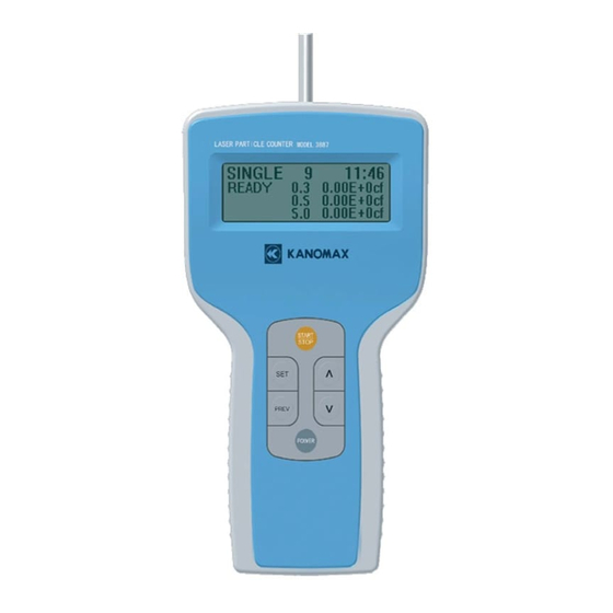
2. Description of Components Inlet 2.83L/min suction volume START/STOP Key To start/stop sampling ENTER Key To execute a menu and enter a setting PREV Key To switch the display screen POWER Key To turn ON/OFF the power. ▲ ▼ Keys Communication Port DC Jack To select a menu and change... - Page 9 Battery Compartment Use four (4) AA rechargeable batteries or alkaline batteries. Operating hours by battery power are only ensured when using the supplied Ni-MH batteries. GlobalTestSupply www. .com Find Quality Products Online at: sales@GlobalTestSupply.com...
-
Page 10: Precautions For Use
3. Precautions for Use The following precautions must be taken when using the instrument. ● Sampling There are possibilities of particle deposit/rescattering when sampling is performed by using a tube connected to the inlet. It is recommended that sampling is performed without using the tube. However, if a tube is required for sampling, the tube recommend below must be used. -
Page 11: Measurement Modes
4. Measurement Modes The instrument is equipped with six (6) measurement modes. ● REPEAT Mode (Suitable for repeated measurement at a same location.) Measurement of a certain sampling period and interval can be repeated from twice to infinite number of times. When storing the measurement data, the maximum number of measurements is 10,000 times. -
Page 12: Repeat Mode
4-1 REPEAT Mode Setup procedure is shown below. (Character positions may not correspond to the actual screen.) Power Up Measurement Setting Screen <MENU> LOC.: 1.MEASURE MODE LOC number can be used for identifying room 2.DATA PROCESSING numbers or measurements. Setting of this item 3.OPTIONS is not mandatory. - Page 13 REPEAT 30B 20:32 READY 0.3 0.00E+0/m3 0.5 0.00E+0/m3 00/02 5.0 0.00E+0/m3 Press START/STOP key REPEAT 30B 20:32 0.3 0.00E+0/m3 The measurement unit can be changed by using the 00:59 0.5 0.00E+0/m3 ▲▼ key. 01/02 5.0 0.00E+0/m3 CNT : Integrated value : Number of particles per one cubic meter.
- Page 14 Cursor Operation The cursor moves each time the “ENTER” key is pressed. LOC.021→LOC.021→LOC.021→STR:N→BEEP:N→ Switch between Y/N by using the ▲▼ key. Change between 0-9 by using the ▲▼ key. SAMPLE 01:00→SAMPLE 01:00→SAMPLE 01:00→SAMPLE 01:00→ Change between 0-9 by using the ▲▼ key. 2TIMES→...
- Page 15 Relation between SAMPL and INT For example, when a measurement is performed with the following setting: REPEAT 0.3/0.5/5.0um LOC.021 STR:N BEEP:N SAMPLE 01:00 2TIMES INT 00:10:00 と設定して Press START/STOP Suspension WAIT: approx. 10sec Sampling for 1min Sampling for 1min Time includes Sampling time and Measurement stops and Sampling suspension time.
-
Page 16: Single Mode
4-2 SINGLE Mode Setup procedure is shown below. (Character positions may not correspond to the actual screen.) Power UP <MENU> Move the 1.MEASURE MODE Measurement Setting Screen cursor by 2.DATA PROCESSING ▲▼key. 3.OPTIONS LOC.: LOC number can be used for identifying room Press ENTER key numbers or measurements. - Page 17 Press START/STOP key SINGLE 30B 20:32 0.3 0.00E+0/m3 00:59 0.5 0.00E+0/m3 01/01 5.0 0.00E+0/m3 SINGLE 30B 20:32 0.3 0.00E+0/m3 0.5 0.00E+0/m3 01/01 5.0 0.00E+0/m3 Cursor Operation The cursor moves each time the “ENTER” key is pressed. LOC.021→LOC.021→LOC.021→STR:N→BEEP:N→ Switch between Y/N by using the ▲▼...
-
Page 18: Cont Mode
4-3 CONT Mode Setup procedure is shown below. (Character positions may not correspond to the actual screen.) Power Up <MENU> Move the 1.MEASURE MODE cursor by 2.DATA PROCESSING Measurement Setting Screen ▲▼key. 3.OPTIONS LOC.: Press ENTER key LOC number can be used for identifying room numbers or measurements. - Page 19 Press START/STOP key CONT 20:32 0.3 0.00E+0/m3 00:01 0.5 0.00E+0/m3 5.0 0.00E+0/M3 Press START/STOP key CONT 20:32 STOP 0.3 0.00E+0/m3 0.5 0.00E+0/m3 5.0 0.00E+0/M3 GlobalTestSupply www. .com Find Quality Products Online at: sales@GlobalTestSupply.com...
-
Page 20: Calc Mode
4-4 CALC Mode Setup procedure is shown below. (Character positions may not correspond to the actual screen.) Power UP <MENU> Move the 1.MEASURE MODE cursor by 2.DATA PROCESSING Measurement Setting Screen ▲▼key. 3.OPTIONS LOC.: Press ENTER key LOC number can be used for identifying room numbers or measurements. - Page 21 Press START/STOP key CALC 20:32 0.3 0.00E+0/m3 09:59 0.5 0.00E+0/m3 01/10 5.0 0.00E+0/M3 Displayed particle size can be changed by using the ▲▼ key. When “STR” is set to “Y”, the data will be stored in the instrument. CALC AVG 1.23E+4/m3 0.3um STD 2.41E+2/m3...
-
Page 22: Remote Mode
4-5 REMOTE Mode Setup procedure is shown below. (Character positions may not correspond to the actual screen.) Power Up <MENU> Move the 1.MEASURE MODE cursor by Measurement Setting Screen 2.DATA PROCESSING ▲▼key. 3.OPTIONS LOC.: LOC number can be used for identifying room Press ENTER key numbers or measurements. - Page 23 Press START/STOP key CALC 20:32 0.3 0.00E+0/m3 09:59 0.5 0.00E+0/m3 01/10 5.0 0.00E+0/M3 Displayed particle size can be changed by using the ▲▼ key. When “STR” is set to “Y”, the data will be stored in the instrument. CALC AVG 1.23E+4/m3 0.3um STD 2.41E+2/m3...
-
Page 24: Iso>4 Mode
4-6 ISO>4 Mode Setup procedure is shown below. (Character positions may not correspond to the actual screen.) Power Up Measurement Setting Screen LOC.: <MENU> LOC number can be used for identifying room 1.MEASURE MODE numbers or measurements. Setting of this item 2.DATA PROCESSING is not mandatory. - Page 25 ISO>4 20:32 READY 0.5 0.00E+0/m3 5.0 0.00E+0/m3 00/02 1POINT Press START/STOP key ISO>4 20:32 0.5 0.00E+0/m3 00:59 5.0 0.00E+0/m3 The measurement unit can be changed by using the 01/02 1POINT ▲▼ key. CNT : Integrated value : Number of particles per one cubic meter. ISO>4 20:32 : Number of particles per 28.3L.
- Page 26 ISO>4 20:32 ISO>4 20:32 0.5 0.00E+0/m3 0.5 0.00E+0/m3 5.0 0.00E+0/m3 Operate by using 5.0 0.00E+0/m3 02/02 FINISH? ▲▼ key 02/02 ERASE DATA? Press ENTER key ISO>4 20:32 0.5 0.00E+0/m3 5.0 0.00E+0/m3 02/02 CALCULATE? ISO>4 20:32 0.5 0.00E+0/m3 5.0 0.00E+0/m3 02/02 EDIT TIMES? 2POINT AVG 6.75E+2/m3...
-
Page 27: View Stored Data
5. View Stored Data Data stored in the LPC can be viewed on the screen or by printing. Displaying on the LPC screen --------------------- View in “DISPLAY” mode. Printing output --------------------------------------- An optional printer and printer cable sold separately are required for printing. GlobalTestSupply www. -
Page 28: Viewing Stored Data On Lpc Screen
5-1 Viewing Stored Data on LPC Screen The data stored in the LPC can be viewed on its screen by the following procedure. Power Up <MENU> 1.MEASURE MODE 2.DATA PROCESSING 3.OPTIONS RECORD.: Number of stored data records. START: Data number of data to be displayed. Press ENTER key <... -
Page 29: Printing Stored Data
5-2 Printing Stored Data Required Items: To print the measured data, a dedicated cable and printer is required. Printer Cable MODEL 3887-07 Printer DPU-H245 Connect the printer cable to the communication connector of the instrument. Power up the printer. (Internal setting is not necessary.) The data stored in the instrument can be printed out from the dedicated printer connected to the instrument by the following procedure. - Page 30 ● Print Example (1) REPEAT, SINGLE, CONTINUOUS Mode 2000 / 03 / 21 16:40 REPEAT RECORDS : 00008 LOCATION : 188 TEST:01:00 INT : 00 : 05 : 30 0.3um 564700 CNT 0.5um 10457 CNT 1.0um 323 CNT (2) CALCULATION Mode 2000 / 03 / 21 16:40 E=LFO...
- Page 31 (3) ISO>4 Mode ISO>4 RECORDS : 00050-00051 LOCATION: 02 2000 / 03 / 21 16 : 40 E=LFO TEST: 01 : 00 INT:00:01:50 TIMES: 02 SIZE 0.5um 564700E+05 /m3 5.0um 10457E+02 /m3 ――― 0.5um ISO>4 MODE RESULT ――― 564700E+05 /m3 10.457E+02 /m3 4.57E+02 /m3 ―――...
-
Page 32: Delete Stored Data
5-3 Delete Stored Data The data stored in the instrument can be deleted by the following procedure. Power Up <MENU> 1.MEASURE MODE 2.DATA PROCESSING 3.OPTIONS Press ENTER key < DATA PROCESSING > RECORDS 99999 1.DISPLAY 3.PRINT 2.UPLINK 4.CLEAR Press ENTER key <DATA CLEAR>... -
Page 33: Useful Functions
6. Useful Functions The LPC is equipped with useful functions as listed below. 1) Alarm Threshold can be set to activate an alarm. 2) Changing measurement unit Measurement unit (/cf, /m , or CNT) can be selected. 3) Calendar Setting Calendar can be adjusted in case the initial setting needs to be adjusted. -
Page 34: Alarm
6-1 Alarm The procedure for setting the alarm is shown below. Power Up <MENU> Alarm level can be set for each particle size as a 1.MEASURE MODE cleanliness criterion. When the set alarm level is 2.DATA PROCESSING crossed, the reading will flash during a 3.OPTIONS measurement. -
Page 35: Changing Measurement Unit
6-2 Changing Measurement Unit The procedure for changing the measurement unit is shown below. Power Up <MENU> 1.MEASURE MODE 2.DATA PROCESSING 3.OPTIONS Press ENTER key < OPTION > 1. ALARM 4. HOTKEY 2. UNITS 5. AUTOST. 3. UTILITIES Press ENTER key <UNITS>... -
Page 36: Calendar Setting
6-3 Calendar Setting The procedure for adjusting the calendar is shown below. Power Up <MENU> Change the value by using the ▲▼ key. 1.MEASURE MODE The cursor can be moved to the next digit by pressing 2.DATA PROCESSING the ENTER key. 3.OPTIONS 2005/08/05 Press ENTER key... -
Page 37: Communication Setting
6-4 Communication Setting The procedure for setting the communication protocol to communicate with a computer is shown below. Power Up Change the values by using the ▲▼ key. Move the cursor to the “ID” row by pressing the ENTER key. <MENU>... -
Page 38: Hotkey
6-5 Hotkey By presetting the HOTKEY function, measurement in the preset measurement mode can be performed on pressing the START/STOP key on the <MENU> screen. Setup procedure is shown below. Power Up <MENU> 1.MEASURE MODE 2.DATA PROCESSING 3.OPTIONS Press ENTER key <... -
Page 39: Automatic Measurement Start
6-6 Automatic Measurement Start Measurement will start automatically when the preset time has expired. Setup procedure is shown below. Power Up <MENU> 1.MEASURE MODE 2.DATA PROCESSING 3.OPTIONS Press ENTER key < OPTION > 1. ALARM 4. HOTKEY 2. UNITS 5. AUTOST. 3. -
Page 40: Error Messages
7. Error Messages When there is an error, the self-diagnosis function displays a symbol on the screen indicating an error (symbol will be displayed where “■” mark is shown below). REPEAT 30B ■ 20:32 | WAIT 0.3 0.00E+0/m3 0.5 0.00E+0/m3 00/02 5.0 0.00E+0/m3 Symbol... -
Page 41: Low Battery Alarm
8. Low Battery Alarm Battery alarm will be displayed when battery capacity drops below a certain level during battery powered operation. When battery voltage drops below 4.2V, battery mark will be displayed at the upper right corner of the screen indicating that the instrument is in the Primary Alarm Level. The instrument will transfer to the Secondary Alarm Level (screen shown on the right) in approx. -
Page 42: Specifications
9. Specifications Product Handheld Laser Particle Counter Model 3887 Measuring Particle 0.3, 0.5, 5.0μm Size (Optional Specification: 0.3, 0.5, 1.0μm) Flow Rate 0.1 cf/min (2.83 L/min) Sampling Time 10 sec to 99min 59sec (1 sec increments) Number of 1 to 99 times or Continuous... -
Page 43: Troubleshooting
10. Troubleshooting If you have a problem with your unit, please check the following list for solutions. Symptom Possible Cause / Solution Refer to The AC adapter is not connected properly. The display does not appear → Confirm the AC adapter and power cable. when the power is turned ON. -
Page 44: Warranty And After Service
When making an inquiry, please provide the following information. * Product Name: Handheld Laser Particle Counter * Model Number: 3887 * Serial Number: xxxxxx * Date of Purchase: Day, Month and Year * Description of Symptom in Detail: GlobalTestSupply www.
Need help?
Do you have a question about the 3887 and is the answer not in the manual?
Questions and answers