Advertisement
Table of Contents
- 1 Exclusion of Liability
- 2 Safety Instructions
- 3 Technical Data and Functions
- 4 General Data
- 5 Functions and Operation
- 6 Mechanical Installation
- 7 Electrical Connection
- 8 Safety Functions
- 9 Cable Routing Recommendations
- 10 Wire Cross Sections
- 11 Handle Bar Controls
- 12 Starting Setup
- 13 Troubleshooting
- 14 Fcc Compliance Statement
- Download this manual
Operating and installation guide
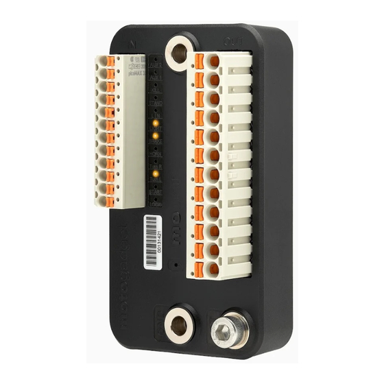
digital control device m.unit blue
valid from serial no. 000xxxxx
(see the serial sticker at the device)
Suchen Sie die deutsche Bedienungsanleitung?
http://motogadget.com/de/elektrik/elektronische-steuerbox-m-unit/downloads.html
_______________________________________________________________
Manual V1.3
0
Advertisement
Table of Contents

Related Manuals for motogadget m.unit blue

Summary of Contents for motogadget m.unit blue
- Page 1 Operating and installation guide digital control device m.unit blue valid from serial no. 000xxxxx (see the serial sticker at the device) Suchen Sie die deutsche Bedienungsanleitung? http://motogadget.com/de/elektrik/elektronische-steuerbox-m-unit/downloads.html _______________________________________________________________ Manual V1.3...
- Page 2 Thank you very much for purchasing a high quality product by motogadget. Please read the following information and recommendations thoroughly and follow these instructions during installation and use of the instrument. No liability is assumed by motogadget for damage or defects resulting from negligence or failure to follow the operating and installation guide.
-
Page 3: Exclusion Of Liability
1 Review Of Delivery All products from motogadget are thoroughly checked to ensure they are completely fault free when dispatched. Please check the received goods immediately for possible transport damage. If you find any damage or other deficiencies, please contact us immediately. -
Page 4: Technical Data And Functions
THE CONNECTOR CABLES ARE FIXED TIGHTLY. 4 Duty Of Registration The m.unit blue does not have to be registered. The user has the responsibility that chosen settings for vehicles rear and brake light are conform to the country laws. The user also has to ensure compliance with local regulation in respect to connection and usage. -
Page 5: Functions And Operation
• integrated digital brake-light modulator with programmable flashing sequence, acceleration- controlled emergency brake-light • pairing of m-unit with other motogadget products via LIN bus • integrated starter relay for solenoid switch (up to 30A switching capacity) • smart and fully configurable load control / shut-off for maximum starting power of battery on starting process •... - Page 6 Therefore no other devices, relays, boxes or units as part of the wiring harness are necessary. A complete new and minimised vehicle wiring can be made with minimal time, materials and effort; compared to conventional solutions, only a fraction of space and cables is needed. State of the art technology like pulse width modulation afford new possibilities like connecting rear and brake light together with only one cable.
- Page 7 Alarm system The sensitivity of the alarm system is independent of its positioning and orientation. If activated, the alarm system will flash all turn indicators when the main switch is deactivated. The vehicle’s relative position and orientation will be recorded and stored and the alarm system engaged. The alarm is triggered when the orientation of the vehicle is changed on it’s X, Y or Z axis (e.
-
Page 8: Mechanical Installation
(connected to the battery via the main fuse) might malfunction and create a short circuit. If cables with a lesser diameter than indicated in Chapter 8.4 are connected (e. g. motogadget instruments or the m-lock), they have to be protected by the included fusible links. -
Page 9: Cable Routing Recommendations
8.4 Cable Routing Recommendations Cables used in vehicles must be suitable for this application. We recommend our cable kit (order # 4002031). Cable insulation must have a adequate thickness and insulation material must have a resistance against fuel, oil, cold and heat. Please use only cables which are certified for use in vehicles. -
Page 10: Handle Bar Controls
8.6 Connecting Battery’s Positive Terminal Cable connection has to be carried out as shown in the drawing at the right side. The minimum wire cross section must no go below 10mm². The cable end has to be supplied with an eyelet and will be mounted with a M5 screw to the m-Unit. - Page 11 7.8 Connecting Load Circuits The m-Unit provides 8 independent circuits which are permanently supervised. At all connected loads were the positive terminal switched, that means, from m-Unit’s output terminal lead one cable to the load which is connected to vehicles earth. At the particular output only the intended load must be connected.
- Page 12 Simplified vehicle circuit diagram with m-Button (optional accessory) The circuit diagram below shows a simplified vehicle wiring loom with use of the m-button. Therefore 6 wires do not apply, because only one cable is needed to connect handle bar controls with m-unit.
- Page 13 AUX 2 Output This output is designed for multiple use and equipped with 2 connecting terminals. Depending on configuration, AUX2 input can be used for switching operations (via button / switch), or switching can be automatically performed. Ignition Lock When using m-Lock as ignition lock, the m-Lock switching output (brown cable) can be connected directly to the m.unit input LOCK.
- Page 14 8.9 Connecting Indicator Lights 9 Setup 9.1 Layout Device setup is structured in menus (1–12) with selectable options (A–J) as follows: Menu 1 – Handlebar Instruments A) configuration A (use of 5 push buttons) B) configuration B (HD and BMW) C) configuration C (Japanese and various European motorbikes) D) configuration D (new Ducati models) E) configuration E (use of 4 push buttons)
- Page 15 Menu 4 – Brake light configuration A) standard (continuous light) B) fade in and fade out with 3Hz C) flashing with 5Hz D) 8 times flashing with 5Hz and continuous light E) 2 times flashing and 1s continuous light, and start again F) 3s continuous light and flashing with 5Hz G) emergency braking –...
-
Page 16: Starting Setup
Menu 11 – Side stand A) input Stand used as N/C contact (engine start enabled when input is open) B) input Stand used as N/O contact (engine start enabled when input switched to ground) Menu 12 – Parking light A) deactive B) active C) 1h active D) 3h active... - Page 17 light, respectively). In case of a defective turn signal light, according to legal regulations the flashing frequency will be doubled. Therefore, every time the existing wiring is changed or a different illuminant is used, the setup needs to be started for re-calibration and exited. 9.5 Example for Setup The following example is demonstrating the operation in setup mode.
-
Page 18: Troubleshooting
Set setup menu item 6 to option A glowing permanently 11.2 Return And Complains When returning your m.unit for technical inspection, please follow the link below: http://motogadget.com/de/repairinquiry The motogadget team wishes you pleasant and safe riding, and lots of fun with your new m.unit. -
Page 19: Fcc Compliance Statement
EU Directive 1999/5/EC. The vehicle body control module integrated in this product has been pre-certified separately and is marked with CE0168 R&TTE directive. Hereby, motogadget declares that motogadget products and accessories are in compliance with the essential requirements and other relevant provisions of the EU Directive 1999/5/EC. - Page 20 If this equipment does cause harmful interference to radio or television reception, which can be determined by turning the equipment off and on, the user is encouraged to try and correct the interference by one or more of the following measures: •...
Need help?
Do you have a question about the m.unit blue and is the answer not in the manual?
Questions and answers