Advertisement
Quick Links
Services Unlimited, Inc./ Parts Guru
Installing thermoblock S-series
S 55-95, X-70-95, Scala,
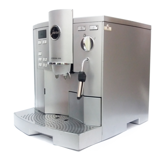
In this guide, the removal and installation of the Thermo Block 96 is described
in a Jura S9. Similar models with fewer features may have different wiring and
hose routing. It is advised the wiring and hose connections are clearly
marked/tagged and pictures taken to not lose the right connections and
positions.
Serviices Unlimited, Inc./ Parts Guru
email: sales@partsguru.com
Ju
r
a
I
m
p
re
s
sa
3
0
0
/
50
0
,
6
4000/6000
For Jura parts, and fast repairs, Contact:
Lansdale, PA 19446
Phone: 215-361-7000 Fax: 215-361-7434
T
h
er
m
o
b
lo
ck
T
B
-
9
6
01
,
E
v
o
lu
t
io
n,
U
l
t
r
a
:
, Cappuccinatore, M30,
1 of 34
Advertisement

Related Manuals for Jura Impressa TB-96


Summary of Contents for Jura Impressa TB-96
- Page 1 In this guide, the removal and installation of the Thermo Block 96 is described in a Jura S9. Similar models with fewer features may have different wiring and hose routing. It is advised the wiring and hose connections are clearly marked/tagged and pictures taken to not lose the right connections and positions.
- Page 2 Services Unlimited, Inc./ Parts Guru Repair of Jura machines is not simple or be taken lightly. Anyone using this repair guide must be experienced in electrical repairs and be familiar with automatic functions of the machine. Inexperienced persons accept the risk of their work & errors causing damage to the machine &/or personal injury.
- Page 3 Services Unlimited, Inc./ Parts Guru Disassembling Most illustration are easy to follow Do not rely on written text alone. Match the text with the picture. Understand the progress of work with every step. Next step: Remove the two Torx (T10) orPhilip screws, shown above email: sales@partsguru.com 3 of 34...
- Page 4 Services Unlimited, Inc./ Parts Guru Pull the side panel slight away at the bottom and lift up to unhook the top two tabs. Next losen the screw to free the TB96 cage email: sales@partsguru.com 4 of 34...
- Page 5 Services Unlimited, Inc./ Parts Guru Take a good look at the position of parts, hoses and wiring. The pump, diaphragm regulator, Power board, Thermo block, steam boiler above Disconnect the blue wire from the solenoid valve coil. email: sales@partsguru.com 5 of 34...
- Page 6 Services Unlimited, Inc./ Parts Guru Then remove the ground wire and then disconnect the next wire as shown. email: sales@partsguru.com 6 of 34...
- Page 7 Services Unlimited, Inc./ Parts Guru Next disconnect the double white, then green & orange wire as shown Disconnect Green ground wires from TB metal housing as shown. email: sales@partsguru.com 7 of 34...
- Page 8 Services Unlimited, Inc./ Parts Guru Press the catches and loosen the wires as shown with arrows. Disconnect the hose from (legris) push connect fitting from the solenoid inlet. Push the ring on the fitting as you pull the hose free. email: sales@partsguru.com 8 of 34...
- Page 9 Services Unlimited, Inc./ Parts Guru Remove the hairpin clip on the diaphragm regulator as shown by the arrow and pull up the hose free. Push the pump to the right and turn it towards you to disconnect the wire from the pump as shown by arrows.Disconnect the wire on the pump.
- Page 10 Services Unlimited, Inc./ Parts Guru Remove the wire that connects to the TB c asing (blue arrow) and leave the other wires at their connections. Disconnect the hose from the Ceramic valve connecting at the (Legris) fitting on TB as shown. Push the ring on fitting as you pull the hose.
- Page 11 Services Unlimited, Inc./ Parts Guru Free the hose from the plastic tie See arrow and the inset. Back here push the sheet metal tab away. See also inset screen detail. email: sales@partsguru.com 11 of 34...
- Page 12 Services Unlimited, Inc./ Parts Guru Use a large screwdriver (here redrawn for clarity), the sheet inwards At this point push the plate spring. email: sales@partsguru.com 12 of 34...
- Page 13 Services Unlimited, Inc./ Parts Guru Now, the cage-free and can be pulled out. Carefully pull the assembly out from the unit. email: sales@partsguru.com 13 of 34...
- Page 14 Services Unlimited, Inc./ Parts Guru Now disconnect the blue connector of TB96 (see arrow) Diconnect the hose from the drain valve to the TB. Push the small ring on the fitting as you pull the hose. email: sales@partsguru.com 14 of 34...
- Page 15 Services Unlimited, Inc./ Parts Guru Remove the hex head bolt as shown. and remove the nut from this side of the plate. email: sales@partsguru.com 15 of 34...
- Page 16 Services Unlimited, Inc./ Parts Guru Remove this screw as shown. Pull plates apart and thus keep space open email: sales@partsguru.com 16 of 34...
- Page 17 Services Unlimited, Inc./ Parts Guru now the Thermo block is free to be pulled out Next loosen the spring to remove temperature sensor. email: sales@partsguru.com 17 of 34...
- Page 18 Services Unlimited, Inc./ Parts Guru Lift the spring with a flat screw driver to pull the temperature sensor free. Now disconnect the black wire as shown email: sales@partsguru.com 18 of 34...
- Page 19 Services Unlimited, Inc./ Parts Guru Finally remove the four nuts Re-assembly Connect the black wire to the new Thermo block email: sales@partsguru.com 19 of 34...
- Page 20 Services Unlimited, Inc./ Parts Guru Lock the thermal sensor back in the fastening clamp spring Tighten the clamp screw making sure that the sensing round section on the wire inside silicone sleeve is under the clamp. The clamp spring or the screw may be different in different models.
- Page 21 Services Unlimited, Inc./ Parts Guru Beide 4-Kant Muttern so einsetzen,dass die gerade Shows from outwardly Depending on the TB96 version there may be just one or two mounting locations. On detailed picture the alternative mounting location is shown. Find the location similar to the old TB96 removed and reverse the steps to tighten the sensor.
- Page 22 Services Unlimited, Inc./ Parts Guru Holding the TB cage pushed apart, insert the ThermoBlock assembly with components in the position as shown. If thermo block is seated correctly, the retaining lugs engage on both ends in the steel cage. Now fasten the hex head bolt back. email: sales@partsguru.com 22 of 34...
- Page 23 Services Unlimited, Inc./ Parts Guru Now replace the fixing screw as shown on the solenoid end. Do not miss to flex outwardly the back plate lug to engage the cage again. See also detail screen (in about as far out of turn). The two pictures show the lugs from two views.
- Page 24 Services Unlimited, Inc./ Parts Guru To connect the Teflon hose into the (Legris) fitting, you need to cut the hose end straight across to ensure tight & even connection across the hose end. (no O-rings used). Push tube in the fitting well inside to connect.
- Page 25 Services Unlimited, Inc./ Parts Guru Insert the TB assembly completely pushed in. make sure that wi are not trapped or caught in the way, as TB is pushed into place As TB cage stops by the push, ensure it engages the retaining lugs push back.
- Page 26 Services Unlimited, Inc./ Parts Guru Now reconnect the hose to the solenoid valve Legris, and steam pipe stuck on the other side. Fasten the plastic tie to the two hoses from the Ceramic valve and the TB back. email: sales@partsguru.com 26 of 34...
- Page 27 Services Unlimited, Inc./ Parts Guru Connect the hose as shown. If permitted by the length of hose, as the hose with a straight cut 3-5 mm. Otherwise, you may see the joint is not tight. Then firmly Push it into the Legrisanschluß. Connect the ground wire to the heater cage.
- Page 28 Services Unlimited, Inc./ Parts Guru Connect the long blue wire back on Solenoid valve coil. Basically all wires should be connected passed behind the hoses. Connect the short blue wire to the terminal TB96 email: sales@partsguru.com 28 of 34...
- Page 29 Services Unlimited, Inc./ Parts Guru Connect the two connectors to the slots to the pins in the respective black plastic connector housing. Re-connect the green and yellow ground wires as shown. email: sales@partsguru.com 29 of 34...
- Page 30 Services Unlimited, Inc./ Parts Guru and then on top of the solenoid valve Now assemble the white plug. Since the plug connects with the locking clip below, have the large plugs (Detail: blue arrow) pointing down. email: sales@partsguru.com 30 of 34...
- Page 31 Services Unlimited, Inc./ Parts Guru Connect the green and red wire connector to the power board. Connect the pump connector from the power supply to the heater. Make ABSOLUTELY SURE that the contact with the plastic protection is all the way pushed to the end. If the metal of the plug come in contact with the metal cage, the ELECTRONIC POWER BOARD WILL BE DESTROYED.
- Page 32 Services Unlimited, Inc./ Parts Guru Now connect the Teflon hose to the diaphragm regulator with Seals and some silicone grease on the gasket. Slide the O-ring first on the hose tip and push deep before locking with hairpin clip. Finally, fix the bracket email: sales@partsguru.com 32 of 34...
- Page 33 Services Unlimited, Inc./ Parts Guru Now from the front, apply the screw to fix the heater cage. Snap the Sidewall on top side hooks. email: sales@partsguru.com 33 of 34...
- Page 34 Services Unlimited, Inc./ Parts Guru Next, screw back the two screws. After screwing in the screw, the unit can be with the instructions for opening and closing the S series again assembled. email: sales@partsguru.com 34 of 34...
Need help?
Do you have a question about the Impressa TB-96 and is the answer not in the manual?
Questions and answers