Table of Contents
Advertisement
Quick Links
Download this manual
See also:
Operating Manual
Advertisement
Table of Contents

Related Manuals for AirStage UTY-DCGY


Summary of Contents for AirStage UTY-DCGY
- Page 1 CENTRAL REMOTE INSTALLATION MANUAL CONTROLLER For authorized service personnel only. UTY-DCGY UTY-DCGG PART NO. RCIM111207...
-
Page 2: Table Of Contents
INSTALLATION MANUAL This mark indicates procedures which, if improperly performed, CENTRAL REMOTE CONTROLLER WARNING might lead to the death or serious Contents injury of the user. SAFETY PRECAUTIONS ……………………………………………… 1 Do not install the unit in the following areas: MAIN UNIT AND ACCESSORIES …………………………………… 1 ▪... -
Page 3: Electrical Requirement
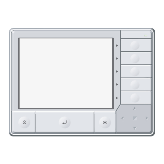
SELECTING AN INSTALLATION LOCATION Name and Shape Q’ty Application Installation This manual 41 11 Dimensions manual Control unit Unit: mm (in.) Operating Instruction book for 25.7(1) manual operation CD-ROM Include the operating manual for Central remote controller Holder For power supply unit installation (Used for (Set) separate type) -
Page 4: Installation Restrictions
41 21 Installation restrictions 51 11 Terminal names Power supply unit Make a service space to perform installation work. Unit: mm (in.) Power supply terminal Power supply terminal Power supply Power supply relay connector output : DC 5V l,N : Power supply 1Ø... - Page 5 ▪ When wiring between the outdoor unit, indoor unit, and WARNING Central remote controller, refer to the indoor unit and When connecting the power supply cable and trans- outdoor unit installation manuals. mission cable, layout the wiring so that the cover of ▪...
-
Page 6: Installation Method
Fig1 61 21 Preparing Installation Separation when terminal block used 6. 2. 1 Controller unit Remove the screw (1 pc). Refrigerant system 1 Remove the claws (2 places) with a flat-blade screwdriver, and separate the front panel and rear panel. Front panel Refrigerant system 2... -
Page 7: Dip Switch Setting
Open the knockouts (2 places), and install the 61 31 DIP Switch Setting one touch bush (2 pcs, accessories). Connect the connector of power supply cable-B CAUTION (accessory) to the relay connector of the cable Use an insulated screwdriver to set the DIP switches. coming from the power supply unit PC board. -
Page 8: Installation Method - Separate Type
Install the power supply unit to a wall. Then in- 61 51 Installation Method - Separate type stall the power supply unit cover and rear panel. Be careful not to pinch the cable. For the cable, use the service parts to connect the power supply unit and control unit. - Page 9 Fix the holder 1 assembly (2 places) with Install the rear panel to a wall. screws (2 pcs x 2 places). Transmission cable Extension cable Power unit cover Holder (accessory) Screw×4 Screw ×4 (When fixing the (accessories) Holder, remove the 4 screws in advance.) Cut the thin part (gray marked part) at the top of the front panel with a cutter.
-
Page 10: External Input/Output Function
Install the screw (1 pc) and fix the panels 6. 6. 3 Apply voltage contact When a power supply must be provided at the input device, connect the connection cables to CN11 and CN12. DC power supply 24V 61 61 External Input/Output function For connection cables, use the specified optional parts. -
Page 11: Turning On The Power
Provide a DC12V power supply. Select a power supply TURNING ON THE POWER capacity with an ample surplus for the connected load. Do not impress a voltage exceeding 12V across pins 1-2, and 3-4 CAUTION The allowable current is DC15mA or less. Provide a load resistance such that the current becomes DC15mA or less.
Need help?
Do you have a question about the UTY-DCGY and is the answer not in the manual?
Questions and answers