Table of Contents
Advertisement
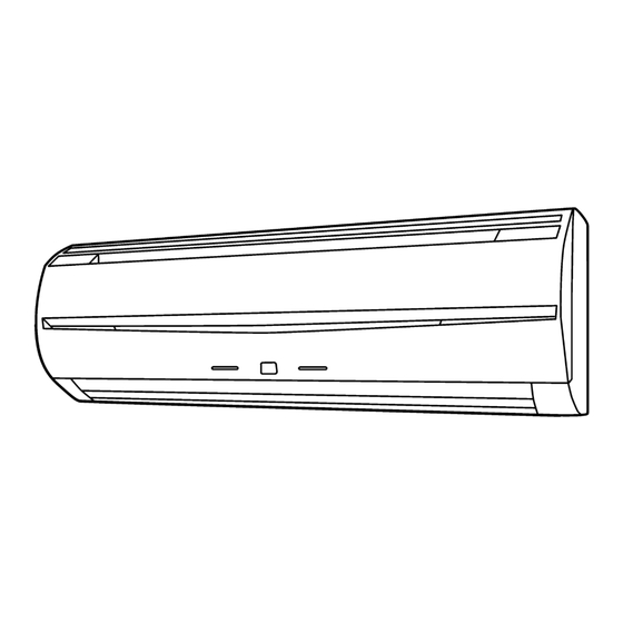
VRF SYSTEM
INDOOR UNIT
Compact Wall Mounted Type Comfort Model
(EEV external model)
INSTALLATION MANUAL
For authorized service personnel only.
Contents
1. SAFETY PRECAUTIONS ............................................. 2
2.1. Precautions for using the R410A refrigerant .......... 2
2.2. Special tool for R410A ............................................ 2
2.3. Accessories ............................................................ 2
3.1. Selecting an installation location ............................ 3
3.2. Installation dimensions ........................................... 4
3.3. Installing the unit .................................................... 4
4.1. Selecting the pipe material ..................................... 7
4.2. Pipe requirement .................................................... 7
4.3. Flare connection (pipe connection) ........................ 7
4.4. Installing heat insulation ......................................... 8
5.1. Electrical requirement ............................................ 9
5.2. Wiring method ...................................................... 10
5.3. Unit wiring ............................................................ 10
6.1. Setting the address .............................................. 11
6.2. Custom code setting ............................................ 13
6.3. Function setting .................................................... 13
(If necessary) .......................................................... 14
6.5. Installing the control unit ...................................... 15
7. FINISHING .................................................................. 16
8. DECORATION PANEL INSTALLATION ...................... 16
9.1. Test operation using PCB (Outdoor unit) .................. 17
9.2. Test operation using Remote Controller ............... 17
10. CHECK LIST ............................................................... 17
11. ERROR CODES ......................................................... 17
PART NO. 9377773043-02
Advertisement
Chapters
Table of Contents

Subscribe to Our Youtube Channel
Related Manuals for Fujitsu ASYE14


Summary of Contents for Fujitsu ASYE14
-
Page 1: Table Of Contents
VRF SYSTEM INDOOR UNIT Compact Wall Mounted Type Comfort Model (EEV external model) INSTALLATION MANUAL For authorized service personnel only. Contents 1. SAFETY PRECAUTIONS ..........2 6. FIELD SETTING 6.1. Setting the address ..........11 2. ABOUT THE UNIT 6.2. Custom code setting ..........13 2.1. -
Page 2: Safety Precautions
1. SAFETY PRECAUTIONS 2.2. Special tool for R410A WARNING • Be sure to read this Manual thoroughly before installation. • To install a unit that uses the R410A refrigerant, use • The warnings and precautions indicated in this Manual dedicated tools and piping materials that have been contain important information pertaining to your safety. -
Page 3: Installation Work
3. INSTALLATION WORK Name and Shape Q’ty Application Operating Manual Especially, the installation place is very important for the split type air conditioner because it is very diffi cult to move from place to place after the fi rst installation. 3.1. -
Page 4: Installation Dimensions
(6) Install the unit where the connection pipe can be easily 3.3.1. Determining the piping direction installed. The piping can be connected in the fi ve directions indicated by 1, (7) Install the unit where the drain pipe can be easily installed. 2, 3, 4, and 5 in (Fig. -
Page 5: Forming The Drain Hose And Pipe
3.3.3. Cutting the hole in the wall for the [Rear piping, Right piping, Bottom piping] connecting piping (1) Install the indoor unit piping in the direction of the wall hole and bind the drain hose and pipe together with vinyl tape. WARNING •... -
Page 6: Installing The Indoor Unit
[Removal method of drain hose] (3) Remove the front panel. 1 The thumb is hung on the lower part as shown in the Remove the screw at the left of drain hose and pull out drain fi gure, and it pulls to the front, pushing [–] mark, and hose. -
Page 7: Pipe Installation
4.2. Pipe requirement 4. PIPE INSTALLATION CAUTION CAUTION • Refer to the Installation Manual of the outdoor unit for • Be more careful that foreign matter (oil, water, etc.) does description of the length of connecting pipe or for difference not enter the piping than with refrigerant R410A models. -
Page 8: Installing Heat Insulation
When the fl are nut is tightened properly by your hand, hold the Dimension A [mm] Pipe outside body side coupling with a separate spanner, then tighten with a Dimension B diameter Flare tool for R410A, torque wrench. [mm] [mm (in.)] clutch type 6.35 (1/4) 9.52 (3/8) -
Page 9: Electrical Wiring
5. ELECTRICAL WIRING CAUTION • Ground the unit. Do not connect the ground cable to a gas pipe, water pipe, WARNING lightning rod, or a telephone ground cable. • Electrical work must be performed in accordance with this Improper grounding may cause electric shock. Manual by a person certifi... -
Page 10: Wiring Method
5.2. Wiring method (EXAMPLE) POWER SUPPLY BREAKER OUTDOOR UNIT EV KIT Loop TRANSMISSION POWER SUPPLY Screw with special washer WALL MOUNTED TYPE INDOOR UNIT INDOOR UNIT Screw with special washer Cable end (Loop) TRANSMISSION TRANSMISSION TRANSMISSION Cable Cable end POWER SUPPLY REMOTE CONTROL POWER SUPPLY POWER SUPPLY REMOTE CONTROL... -
Page 11: Field Setting
Tightening torque 6.1. Setting the address M4 screw 1.2 to 1.8 N·m (Power supply /L, N, GND) (12 to 18 kgf·cm) Manual address setting method CAUTION 5.3.2. Transmission and Remote control cable • When setting the DIP switch, use an insulated screw driver. •... - Page 12 (6) Set the switches on the PCB. Rotary Rotary 1 Indoor unit address Address Address Switch Setting Switch Setting Rotary switch (IU AD × 1)...Factory setting “0” Rotary switch (IU AD × 10)...Factory setting “0” REF AD SW IU AD SW Refrigerant When connecting multiple indoor units to one refrigerant Indoor unit...
-
Page 13: Custom Code Setting
Function details 6.2. Custom code setting Function Setting Selecting the custom code prevents the indoor unit mix-up. Function Default Details number number (Up to 4 codes can be set.) ○ Adjust the fi lter cleaning interval Perform the setting for both the indoor unit and the remote Default Filter notifi... -
Page 14: Connecting The Wired Remote Controller (If Necessary)
6.3.2. Checking the function settings (2) Others • Press and hold the “MANUAL AUTO” button on the indoor Indication pattern unit for 3 seconds to check the function settings. It is Indicator Name Indication pattern necessary to disconnect the power in order to return to OPERATION Function number;... -
Page 15: Installing The Control Unit
Connector Binder To EV kit 6.5. Installing the control unit Refer to 6.1 (1) ~ (5) to install the control unit, thermistor, and grounding wire. • (1) Connect the connection cable. NO GOOD Cable Cable Screw hole Screw hole Do not route the cables over the screw hole. L, N: Power supply cable EV kit cable X1, X2: Transmission cable... -
Page 16: Finishing
(7) Install the front panel. 7. FINISHING • Firstly, fi t the lower part of the front panel, and insert top and bottom hooks. (Three top sides, six bottom sides) After completing the refrigerant leak check (for • Bottom hooks (Six position) details, refer to the Installation Manual of the outdoor unit), install the insulation. -
Page 17: Test Operation
9. TEST OPERATION 11. ERROR CODES If you use a wired type remote control, error codes will appear 9.1. Test operation using PCB (Outdoor unit) on the remote control display. If you use a wireless remote control, the lamp on the photodetector unit will output error codes by way of blinking patterns. - Page 19 VRF 系统 室内机 小型挂壁式 静音型 (EEV 外部机型) 安 装 说 明 书 仅针对授权的专业维修人员。 目录 1. 安全注意事项 ..............2 6. 现场设置 6.1. 设置地址 .................9 2. 关于机组 6.3. 功能设置 ..............11 2.1. 使用 R410A 制冷剂时的注意事项 ........2 6.2. 用户代码设置 ...............11 2.2. R410A 的专用工具 ............2 6.4.
-
Page 20: 安全注意事项
1. 安全注意事项 2.2. R410A 的专用工具 警告 • 安装之前务必彻底阅读该说明书。 • 若安装使用 R410A 制冷剂的机组,请使用专门为 R410A 制造 • 该说明书指出的警告和注意事项包含与您的安全密切相关的 的专用工具和管道材料。 重要信息。请务必遵循这些信息。 因为 R410A 制冷剂的压力大约比 R22 高 1.6 倍,所以未能使 • 将该说明书与操作手册交给用户。 用专用管道材料或不适当的安装可能造成破裂或伤害。 请用户将它们收藏好,以便日后使用,例如更换机组位置或 而且,可能造成严重的事故,例如漏水、电击或火灾。 对机组进行修理。 该标志表示如果步骤执行失当, 可能会导 工具名称 变更内容 警告! 致用户死亡或严重伤害。 • 压力较高, 不能使用传统的压力计测量。 为 •... -
Page 21: 安装工作
名称及形状 数量 应用 3. 安装工作 布带 用于安装室内机 对于分体式空调,安装地点尤为重要,因为首次安装后,移 动位置非常困难。 3.1. 选择安装位置 自攻螺钉 用于安装壁挂支架 (M4 × 25mm) 警告 • 选择能有效支撑室内机重量的安装位置。将机组安装牢固,以 免倾倒或坠落。 线束 用于安装有线遥控器 注意 • 请勿将机组安装在下列区域 : • 盐含量高的区域,例如海边。 这会损坏金属部件,使部件掉落或使机组漏水。 • 充满矿物油或包含大量溅油或蒸气的区域,例如厨房。 这会损坏塑料部件,使部件掉落或使机组漏水。 空气过滤网 • 会产生对设备有负面影响的物质(例如硫磺气体、氯气、酸 或碱)的区域。 这会腐蚀铜管和铜焊接合,从而造成制冷剂泄漏。 • 会造成可燃气体泄漏、包含悬浮碳化纤维或易燃灰尘或挥发 性可燃物(例如涂料稀释剂或汽油)的区域。 如果气体泄漏并留在机组周围,就可能造成火灾。... -
Page 22: 安装尺寸
3.3.2. 安装壁挂支架 3.2. 安装尺寸 注意 提供用于检查的维修空间。 • 安装壁挂支架应横平坚直。 切勿在维修空间布置线路或照明设施,否则会妨碍维修。 壁挂支架 (1) 安装壁挂支架时要保证其水平和垂直位置正确。如果壁挂支 50 mm 架倾斜,水会滴到地上。 或以上 60 mm 或以上 (2) 安装壁挂支架时要保证其足够坚固,能够承受一个成人的体 90 mm 或 重。 以上 • 将至少 6 个螺钉穿过托架外沿附近的孔中,固定壁挂支 架。 • 检查壁挂支架有无嘎吱声。 中心缺口 壁挂支架 1,500 mm 或以上 ( 墙壁帽 ) 1,800 mm 或以上... - Page 23 3.3.4. 安装排水软管和管路 [ 排水软管的拆卸方法 ] 拆下排水软管左侧的螺钉,拉出排水软管。 注意 排水软管 螺钉 • 为了对准排水软管和排水帽,必须牢靠地垂直插入。插入倾 斜会引起漏水。 • 插入时,不得沾有除水以外的其它材料。如果沾有其它材料, 会引起变质和漏水。 • 拆下排水软管后,切勿忘记安装排水帽。 排水定位器(蓝色) • 必须用胶带将排水软管固定在管路底部。 [ 排水软管、的安装方法 ] [ 后管、右管、底部管 ] 垂直向内侧插入排水软管,使排水定位器(蓝色)与排水阀周围 的螺钉孔精确对准。 (1) 按照墙壁孔的方向安装室内机管路,用聚氯乙烯绝缘带将排 请在插入后和更换前将拆下的螺钉重新装好固定。 水软管和管路固定在一起。 排水定位器(蓝色) 螺钉 螺钉孔 排水软管 用聚氯乙烯绝缘带固定 右管 排水阀 管路(顶部)后管 •...
-
Page 24: 管道安装
3 向前拉前面板,抬起上面,将前面板拆下。 • 使用带防水绝热材料的管道。 前面板 注意 • 请在气体和液体管道周围安装绝热材料。否则可能会导致漏 水。 请使用抗热能力超过 120℃的绝热材料。 (仅限逆循环型) 此外,如果安装制冷剂管道的地方的湿度可能会超过 70%, 请 在 制 冷 剂 管 道 周 围 安 装 绝 热 材 料。 如 果 预 计 的 湿 度 为 (4) 将垫片等插入室内机与壁挂支架之间,将室内机的底部与墙 70-80%,请使用 15 mm 或更厚的绝热材料 ; 如果预计的湿度 壁隔开。... -
Page 25: 安装绝热材料
4.3.2. 弯管加工 检查是否漏气后,用接管绝热材料在室内机接管的两个部分 (供气和供液)缠绕绝热材料进行绝热。 • 如果用手使管道成形,注意请勿将它们压扁。 安装接管绝热材料后,用聚氯乙烯绝缘带缠绕两端使其不留 • 弯曲管道时角度不应超过 90°。 缝隙。 • 如果反复弯曲或拉伸管道,材料将变硬,以至很难再次弯曲或 拉伸。 • 弯曲或拉伸管道的次数不应超过三次。 注意 • 为了防止管道破裂,应避免过度的弯曲。 • 如果管道在同一位置反复弯曲,它会破裂。 注意 • 必须紧密贴在主机上不留缝隙。 4.3.3. 管道连接 注意 5. 电气接线 • 连接的 EV 组件(选购)必须适用于室内机。 有关安装说明,请参见 EV 组件的安装说明书。 警告 • 必须使管路正确对准室内机的端口。如果定心不正确,扩口 螺母将无法顺利拧紧。如果强制拧紧扩口螺母,会损坏螺纹。 •... -
Page 26: 电气要求
5.3. 机组接线 注意 • 将机组接地。 请勿将地线连接到气体管、水管、避雷针或电话地线。 • 将电线连接到接线板之前。 不适当的接地可能造成电击。 5.3.1. 电源线 • 请勿将电源线连接到信号线或遥控器接线端,因为这会损坏该 产品。 • 绝不要将电源线和信号线束在一起。将这些线束在一起会导致 错误运行。 • 操作 PCB 时,机身上的静电可能造成控制 PCB 发生故障。请 遵循下列注意事项 : 地线 • 对室内和室外机组以及外围设备使用接地线。 • 切断电源(断路器) 。 • 请触摸室内和室外机组金属部分 10 秒以上,以释放机身静 电源线 电。 A. 对于实心接线 • 请勿触碰接线 PCB 上的部件端子和布线模式。 (1) 要连接电气端子,... -
Page 27: 现场设置
B. 对于绞合线 • 如图 C 所示连接遥控和传输电缆。 图 C (1) 使用下图中所示的带有绝缘套管的环形端子连接接线盒。 (2) 使用适合的工具将环形端子牢固地夹紧到电线,这样电线就 不会松散。 (3) 将指定的电线牢固地连接,并将其固定,使端子上没有压力。 (4) 使用适合的螺丝刀拧紧端子螺钉。 请勿使用过小的螺丝刀,否则可能会损坏螺钉头并造成螺钉 无法正确紧固。 直径不同 连接到同 (5) 请勿将端子螺钉拧得过紧,否则螺钉可能会破裂。 一端 正确 不正确 不正确 (6) 请参见表中的端子螺钉拧紧扭矩。 (7) 请不要用一颗螺丝固定两根电源线。 警告 • 将端子螺钉拧紧到指定的扭矩,否则可能会发生异常过热并可 能导致机组内部的严重损坏。 环形端子 拧紧扭矩 套管 M4 螺钉 0.8 至... - Page 28 (1) 拆下线夹。 旋转开关 示例 : “0” 旋转开关 示例 : “0” 线夹 旋转开关 示例 : “0” Dip 开关 “SET 3” 螺钉 (2) 拆下热交换器的螺钉,然后拆下地线。 表 A (3) 拆下 3 个热敏电阻。 设置 (4) 拆下插头。 设置 开关类型 范围 设置示例 室内机地址 0–63 热敏电阻 IU AD×10 IU AD×1 螺钉...
-
Page 29: 功能设置
表 B 3 遥控器地址 旋转开关 (RC AD SW) ..出厂设定为“0” 用户代码 将多台室内机连接到一个标准有线遥控器时,请从 0 开始 A (出厂设置) 顺次设置 RC AD SW 处的地址。 DIP SW 关 (OFF) 开 (ON) 关 (OFF) 开 (ON) SET 3 SW1 设置 DIP SW 设置 开关类型 关 (OFF) 关... -
Page 30: 连接有线遥控器 ( 根据需要 )
6.3.1. 按钮名称和功能 (2) 其它 指示方式 指示器名称 指示方式 运 转(OPERATION) 功能号码 ; 10 处 指示灯(绿色) (0.5 秒开/ 0.5 秒关) 定时器(TIMER) 功能号码 ; 1 处 指示灯(橙色) (0.5 秒开/ 0.5 秒关) 过滤网(FILTER) 设置号码 : (0-9) 指示灯(红色) (0.5 秒开/ 0.5 秒关) (示例)功能 : 31,设置号码 : 2 12 秒... -
Page 31: 安装控制单元
6.5. 安装控制单元 • 要安装控制单元、热敏电阻和地线,请参见图 6.1(1)至(5) 。 (1) 连接连接电缆。 正确 不正确 导线 螺钉孔 导线 螺钉孔 切勿使导线穿过螺钉孔。 L, N: 电源线 EV 组件线 X1, X2: 信号线 EV 组件线 连接 EV 组件线后,将管子(包含 EV 组件)推 过插头对其进行保护。 连接 连接 管子 绑扎件(小) (2) 安装线夹。 线夹 螺钉 Sc-13... -
Page 32: 完成
顶部挂钩(两侧) 7. 完成 顶部挂钩(中心) 顶部孔(中心) 前面板 完成制冷剂泄漏检查后 (有关详细信息, 请参见室 • 外机的安装说明页), 安装绝热材料。 (1) 在管路之间安装绝热材料。 • 对于后管、右管和底部管,将连接管的绝热材料和室内机 顶部孔(两侧) 室内机 管路的绝热材料搭接在一起,用聚氯乙烯绝缘带固定,使 其没有缝隙。 • 固定 4 个螺钉。 • 对于左管和左后管,将接连接管的绝热材料和室内机管路 (8) 安装回风格栅。 的绝热材料对接在一起,用聚氯乙烯绝缘带固定,使其没 • 将回风格栅的固定轴安装在面板上。 有缝隙。 • 放下回风格栅。 搭接绝热材料 连接管 (9) 将排水软管固定到外墙壁等处。 (绝热材料) 检查排水软管的情况,确保其方向正确。 室内机管路(绝热材料)... -
Page 33: 检查项目表
有线遥控器显示 10. 检查项目表 故障代码 安装室内机 (组) 时, 请特别注意以下的检查项目。 安装完成后, 请确保再次检查以下的检查项目。 检查项目 如果未正确执行 检查框 正确地安装了室内机了 振动, 噪音, 室内机可能 吗? 掉落 已检查气体泄漏 (制冷剂管 无制冷, 无制热 道) 了吗? 已完成绝热工作了吗? 漏水 室内机组排水容易吗? 漏水 电源电压与室内机标签上 不运转, 发热或烧坏 显示的相同吗? 电线和管道全都连接正确 不运转, 发热或烧坏 吗? 室内机接地了吗? 短路 连接电缆具有规定的粗细 不运转,...
Need help?
Do you have a question about the ASYE14 and is the answer not in the manual?
Questions and answers