Table of Contents
Advertisement
Quick Links
Download this manual
See also:
Installation Manual
ARXA24GALH
ARXA30GALH
ARXA36GALH
ARXA45GALH
ARXB24GALH
ARXB30GALH
ARXB36GALH
ARXB45GALH
TM
INSTALLATION MANUAL
INSTALLATIONSANLEITUNG
MANUEL D'INSTALLATION
APPAREIL INTÉRIEUR (type conduit)
MANUAL DE INSTALACIÓN
Únicamente para personal de servicio autorizado.
MANUALE DI INSTALLAZIONE
A uso esclusivo del personale tecnico autorizzato.
ΕΓΧΕΙΡΙΔΙΟ ΕΓΚΑΤΑΣΤΑΣΗΣ
ΕΣΩΤΕΡΙΚΗ ΜΟΝΑΔΑ (Τύπος αγωγού)
Μόνο για εξουσιοδοτημένο τεχνικό προσωπικό.
MANUAL DE INSTALAÇÃO
UNIDADE INTERIOR (Tipo de tubagem)
РУКОВОДСТВО ПО УСТАНОВКЕ
Только для авторизованного обслуживающего персонала.
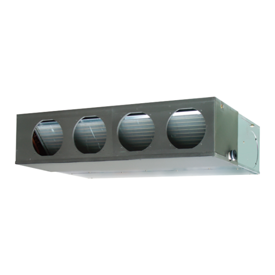
INDOOR UNIT (Duct type)
For authorized service personnel only.
INNENGERÄT (Kanaltyp)
Nur für autorisiertes Fachpersonal.
Pour le personnel agréé uniquement.
UNIDAD INTERIOR (Tipo conducto)
UNITÀ INTERNA (tipo a condotto)
Apenas para técnicos autorizados.
ВНУТРЕННИЙ МОДУЛЬ (Короб)
MONTAJ KILAVUZU
İÇ ÜNİTE (Kanal tipi)
Yalnızca yetkili servis personeli için.
PART NO. 9373385141
Advertisement
Table of Contents

Subscribe to Our Youtube Channel
Related Manuals for AirStage ARXA24GALH


Summary of Contents for AirStage ARXA24GALH
-
Page 1: Installation Manual
Nur für autorisiertes Fachpersonal. MANUEL D’INSTALLATION APPAREIL INTÉRIEUR (type conduit) Pour le personnel agréé uniquement. MANUAL DE INSTALACIÓN UNIDAD INTERIOR (Tipo conducto) ARXA24GALH Únicamente para personal de servicio autorizado. ARXA30GALH MANUALE DI INSTALLAZIONE ARXA36GALH UNITÀ INTERNA (tipo a condotto) ARXA45GALH A uso esclusivo del personale tecnico autorizzato. -
Page 2: Table Of Contents
INSTALLATION MANUAL This mark indicates procedures which, if improperly performed, CAUTION might possibly result in personal harm to the user, or damage to PART NO. 9373385141 property. VRF system indoor unit (Duct type) Read carefully all security information before use or install the air conditioner. Contents Do not attempt to install the air conditioner or a part of the air conditioner by yourself. -
Page 3: Accessories
2.3. Accessories Drain hose insulation Insulates the drain hose and drain WARNING For installation purposes, be sure to use the parts supplied by the manufacturer or Wire Attached only ARXB24/30/36/45L other prescribed parts. model. The use of non-prescribed parts can cause serious accidents such as the unit to fall, Use for static pressure under 40 Pa. -
Page 4: Installation Work
3. INSTALLATION WORK 300 mm Correct initial installation location is important because it is diffi cult to move unit after it is Service hole or more installed. Control box 3.1. Selecting an installation location WARNING Select installation locations that can properly support the weight of the indoor. Install 500 mm the units securely so that they do not topple or fall. - Page 5 WARNING CAUTION When fastening the hangers, make the bolt positions uniform. When air is taken in from the bottom side, the operating sound of the product will easily eater the room. The distance of is adjustable according to the place of the hanging bolts. Install the product and intake grilles where the affect of the operating sound is small.
-
Page 6: Pipe Installation
CAUTION 4. PIPE INSTALLATION To prevent people from touching the parts inside the unit, be sure to install grilles on the inlet and outlet ports. The grilles must be designed in such a way that cannot be removed without tools. CAUTION The static pressure outside the unit is as follows. -
Page 7: Installing Heat Insulation
4.3.1. Flaring Tighten with 2 wrenches. Holding wrench • Use special fl are tool exclusive for R410A. (1) Cut the connection pipe to the necessary length with a pipe cutter. (2) Hold the pipe downward so that cuttings will not enter the pipe and remove any Flare nut Torque wrench burrs. - Page 8 (Right side) Applying 240 mm area of Joint pipe adhesive Hard PVC side (Field supply) Drain pipe (VP25) (Field supply) 4 mm or less Wrap the Drain hose insulation around the drain hose connection. Liquid pipe Drain hose insulation Gas pipe (Accessories) Drain port Drain pan...
-
Page 9: Electrical Wiring
Securely install the electrical box cover on the unit. Model An improperly installed electrical box cover can cause serious accidents such as electric shock or fi re through exposure to dust or water. ARXA24GALH 1.07 A ARXA30GALH 1.08 A Install sleeves into any holes made in the walls for wiring. Otherwise, a short circuit could result. -
Page 10: Wiring Method
WARNING 6.2. Wiring method When using solid core cables, do not use the ring terminal. If you use the solid core cables with the ring terminal, the ring terminal's pressure bonding may malfunction and EXAMPLE cause the cables to abnormally heat up. Outdoor unit or RB unit *1 B. -
Page 11: Connection Of Wiring
Tightening torque M3 screw 0.5 to 0.6 N·m (Transmission /X1, X2) (5 to 6 kgf·cm) (Remote controller /Y1, Y2, Y3) CAUTION To peel the fi lm from the lead cable, use a dedicated tool that will not damage the conductor cable. When installing a screw on the terminal block, do not cut the cable by overtightening the screw. -
Page 12: External Input And External Output (Optional Parts)
6.6. External input and external output (Optional DC power supply P.C.B 12 to 24V parts) Load resistance CNA01 Controller PCB Output terminal (CNB01) P.C.B Apply voltage terminal Load (CNA03) resistance CNA01 (CNA01) Dry contact terminal P.C.B connected unit (CNA02) (CNA04) CNA01 ●... - Page 13 [In the case of “Pulse” input] ● When connecting with unit equipped with a power supply Connector Input signal Command P.C.B OFF → ON Operation Connected CNA01 or CNA02 device 1 OFF → ON Stop Connected device 2 * The last command has priority. Connected * The indoor units within the same remote controller group operates in the same mode.
-
Page 14: Remote Sensor (Optional Parts)
6.7. Remote sensor (Optional parts) 6.8. IR receiver unit (Optional parts) • For the installation method, please refer to the INSTALLATION MANUAL of remote • For the installation method, please refer to the INSTALLATION MANUAL of IR receiver sensor. unit. Connection methods Connection methods •... -
Page 15: Drain Pump Unit (Optional Parts)
6.9. Drain pump unit (Optional parts) 7.1. Setting the address Manual address setting method • For the installation method, please refer to the INSTALLATION MANUAL of drain pump • If the receiver unit is attached, the indoor unit address and the refrigerant circuit unit. -
Page 16: Custom Code Setting
(3) Remote controller address 7.3. Switching the upper limit of cooling i) 3-wire type Rotary switch (RC AD SW)...Factory setting “0” temperature When connecting multiple indoor units to 1 standard wired remote controller, set the address at RC AD SW in sequence from 0. This setting can be raised the upper limit of the cooling temperature setting range. -
Page 17: Test Run
10. ERROR CODES Enable or disable automatic Enable system restart after a power Auto restart ○ Disable outage. If you use a wired type remote controller, error codes will appear on the remote control- ○ ler display. If you use a wireless remote controller, the lamp on the photodetector unit Restrain the cold airfl... - Page 18 Wired Remote Controller Display UTY-RNKY / UTY-RNKG / UTY-RNKYT (3-wire type) Error code URY-RNRY / UTY-RNRG (2-wire type) Touch the [Next Page] (or [previous page]) Error icon to switch to other indoor unit information. Touch the [Status]. Touch the [Error Information]. 2-digit numbers are corresponding to the error code in the preceding table.
Need help?
Do you have a question about the ARXA24GALH and is the answer not in the manual?
Questions and answers