
Related Manuals for SICK RFH620


Summary of Contents for SICK RFH620
- Page 1 Operating Instructions O P E R A T I N G I N S T R U C T I O N S RFH620 RFID RFH620 write/read device (HF) RFID WRITE/READ DEVICE (HF)
- Page 2 Windows XP, Vista, 7, 8, 10 and Internet Explorer are registered trademarks or trademarks of the Microsoft Corporation in the USA and other countries. 8013105/ZO93/2017-09-21 © SICK AG · Germany · All rights reserved · Subject to change without notice...
-
Page 3: Table Of Contents
Checking the incremental encoder..............59 Replacing an RFH620..................59 Troubleshooting.......................61 Overview of errors and malfunctions which could occur......61 Detailed malfunction analysis................61 Status protocol ....................62 SICK support....................62 8013105/ZO93/2017-09-21 © SICK AG · Germany · All rights reserved · Subject to change without notice... - Page 4 Overview of the Appendixes................67 11.2 Configuring the RFH620 with command strings .......... 67 11.3 Dimensional drawing accessories..............68 11.4 EU Declaration of Conformity................. 68 8013105/ZO93/2017-09-21 © SICK AG · Germany · All rights reserved · Subject to change without notice...
-
Page 5: Figures And Tables
Rich Text Format (standardised document format with format description) Secure Digital Start Of Frame SOPAS-ET SICK Open Portal for Application and Systems Engineering Tool (PC software for Windows for confi- guring the RFH620) Progammable Logic Controller Start Of Text 8013105/ZO93/2017-09-21... - Page 6 Figures and Tables Chapter Operating Instructions RFID RFH620 write/read device (HF) TCP/IP Transmission Control Protocol/Internet Protocol Tag IDentifier Unique IDentification code 8013105/ZO93/2017-09-21 © SICK AG · Germany · All rights reserved · Subject to change without notice...
-
Page 7: Tables
Default setting for the SOPAS-ET configuration software (excerpt) ..... 52 Tab. 7-2: Connection between PC with SOPAS-ET configuration software and the RFH620 ...................... 53 Tab. 10-1: Technical specifications of the RFH620 ............64 8013105/ZO93/2017-09-21 © SICK AG · Germany · All rights reserved · Subject to change without notice... -
Page 8: Figures
Serial version: Dimensions of the RFH620-1000001 ........65 Fig. 10-2: Ethernet version: Dimensions of the RFH620-1001201....... 66 Fig. 11-1: Dimensions of the fixing bracket no. 2048551 ..........68 8013105/ZO93/2017-09-21 © SICK AG · Germany · All rights reserved · Subject to change without notice... -
Page 9: Notes On This Document
SOPAS-ET configuration software contains an online help system to facilitate configuration. Important Further information about the design of the RFH620 as well as the RFID technology is avail- able at SICK AG, Auto Ident division. On the Internet at www.sick.com. -
Page 10: Used Symbols
Used symbols To gain easier access, some information in this documentation is emphasised as follows: Notice! Notice indicates a potential risk of damage or impair on the functionality of the RFH620 or other devices. Carefully read and follow the notice details! Warning notice! A warning notice indicates real or potential danger. -
Page 11: For Your Safety
For correct and safe functioning, the RFH620 must be installed, operated and maintained by sufficiently qualified staff. Important Repairs to the RFH620 should only be carried out by qualified and authorised SICK AG ser- vice staff. The operating instructions should be made available to the end user. -
Page 12: Intended Use
Important Any warranty claims against SICK AG shall be deemed invalid in case changes are made to the RFH620, e. g., opening the housing, this includes modifications during installation and electrical installation or changes to the SICK software. -
Page 13: General Safety Precautions And Protection Measures
General safety precautions and protection measures Read the general safety precautions thoroughly and observe them during all operations on the RFH620. Also observe the warning notices in each chapter of this document be- fore the standard operating procedures. Electrical installation work... -
Page 14: Quick Stop And Quick Restart
Typical 5 W in 10 V ... 30 V DC (in unwired switching outputs) 2.5.2 Dispose of the device after decommissioning Currently, SICK AG will not accept the return of any devices which can no longer be operated or repaired. Irreparable devices must be disposed of in an environmentally friendly manner and in accordance with valid country-specific waste disposal guidelines. -
Page 15: Quick-Start
Additional accessories required (not in the scope of delivery) • Connection module CDB620 or CDM420 • For the Ethernet version of the RFH620: Connection cable for data and function inter- faces (see ordering information on the product page at the Internet under: www.sick.com/rfh6xx) •... -
Page 16: Performing The Reading
Fig. 3-2: Advanced settings on the Performance Optimization register tab 2. Carry out test reading with transponder. To this end, hold the transponder in the reading area of the RFH620 and trigger the reading by clicking on START The unique ID, manufacturer and IC type of the detected transponder are registered. - Page 17 1. Correct or optimise the parameter values, where necessary, via the SOPAS-ET configu- ration software. 2. In order to optimise the RSSI value, reduce the distance between the RFH620 and the transponder. Reading/writing the user data of the transponder...
- Page 18 Quick-Start Chapter 3 Operating Instructions RFID RFH620 write/read device (HF) 8013105/ZO93/2017-09-21 © SICK AG · Germany · All rights reserved · Subject to change without notice...
-
Page 19: Product Description
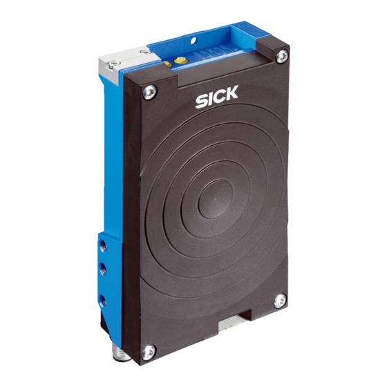
All the components are located in a housing suitable for the industry. Depending on the version, the electric connection of the RFH620 takes place via a cable with a connector or a revolving connector unit with two connections. - Page 20 Button for function selection/activation Type plate Micro SD memory card (optional) LEDs for status indicator Antenna Fig. 4-1: Serial version: Device view of the RFH620-1000001 8013105/ZO93/2017-09-21 © SICK AG · Germany · All rights reserved · Subject to change without notice...
- Page 21 Micro SD memory card (optional) LEDs for status indicator 4-pole M12 female connector (Ethernet connection) Antenna 12-pole M12 male connector Fig. 4-2: Ethernet version: Device view of RFH620-1001201 8013105/ZO93/2017-09-21 © SICK AG · Germany · All rights reserved · Subject to change without notice...
-
Page 22: Scope Of Delivery
• Future proof due to firmware update (flash PROM) via data interface • Future-proof SOPAS-ET configuration software • Low current consumption • Extended power supply range 8013105/ZO93/2017-09-21 © SICK AG · Germany · All rights reserved · Subject to change without notice... -
Page 23: Tab. 4-3: Overview Of The Product Features And Functions Of The Rfh620
SICK-specific CAN-SENSOR network • Optional bus connection module CDF600 for PROFIBUS-DP Tab. 4-3: Overview of the product features and functions of the RFH620 8013105/ZO93/2017-09-21 © SICK AG · Germany · All rights reserved · Subject to change without notice... -
Page 24: Functions Of The Rfh620
Serial version: Electric connections to the RFH620 with connection cable Write/read device Fig. 4-4: Serial version: Electric connections to the RFH620 with connection cable by using a CDF600 bus connection module 8013105/ZO93/2017-09-21 © SICK AG · Germany · All rights reserved · Subject to change without notice... - Page 25 Write/read device Fig. 4-5: Ethernet version: Electrical connections to the RFH620 with connector unit The detailed wiring of the RFH620 and the connections to the host/PC and to the external sensors is described in chapter 6 Electrical installation, page Note...
-
Page 26: Tab. 4-4: Configurable Functions Of The Rfh620
RFH620, the two outputs are only available with the connection module CDB620/CDM420 in combination with the parameter memory module CMC600. Tab. 4-4: Configurable functions of the RFH620 8013105/ZO93/2017-09-21 © SICK AG · Germany · All rights reserved · Subject to change without notice... -
Page 27: Control Elements And Indicators
The RFH620 operates fully automated in normal operation. 4.7.2 LEDs on the RFH620's housing The RFH620's housing has six LEDs that display the operating status, the RF activity, the status of the reading result as well as transfer to the RS-232/RS-422/485, CAN and Ether- net data interfaces. -
Page 28: Tab. 4-6: Meaning Of The Leds During Activation Of Buttons
RFID RFH620 write/read device (HF) 4.7.3 Buttons on the RFH620's housing There are two yellow buttons on the RFH620´s housing in the LED area (see chapter 4.2.1 Serial version: Device view of RFH620, page 20). You can call up predefined functions via these buttons. - Page 29 Furthermore, the RFH620 remains in reading operation. • In case a user logs onto the RFH620 in button operating mode, the RFH620 leaves the button operating mode and restarts the reading operation. The beeper confirms the change with a descending melody.
- Page 30 Product description Chapter 4 Operating Instructions RFID RFH620 write/read device (HF) 8013105/ZO93/2017-09-21 © SICK AG · Germany · All rights reserved · Subject to change without notice...
-
Page 31: Installation
• Install the reading pulse sensor for reading pulse triggering Important Do not open the RFH620's housing. If the device is opened, the SICK AG warranty shall not apply. Installation preparations In general, the following requirements should be observe for the installation: •... - Page 32 Stable mounting device – Adjustable alignment of the RFH620 in the x and y axis – The mounting device must be able to bear the weight of the RFH620 including its connection cable (depending on the device version) without vibrating.
-
Page 33: Installation Location
1. Prepare base for the installation of the RFH620 holder, see chapter 5.2.3 Mounting de- vice, page 2. Install the RFH620 holder on the base. 3. Screw M6 bolts through the holder and into the RFH620's blind hole taps and gently tighten them. Installing external components 5.5.1... -
Page 34: Dismantling The Rfh620
RFID RFH620 write/read device (HF) 5.5.2 Installing the external reading pulse sensor If the RFH620 is triggered by an external reading pulse sensor (photoelectric reflex switch), the sensor has to be installed close to the RFH620. Important An overview about available photoelectric switches and photoelectric proximity switches as well as the associated accessories (brackets, connection cables) is availabe from the follo- wing product internet page: www.sick.com/rfh6xx... -
Page 35: Electrical Installation
Connection cables: refer to the ordering information on the product page at the Internet under: www.sick.com/rfh6xx Important The possible distance between the RFH620 and the host computer depends on the physical design of the selected host interface and the set data transfer rate. The following tools are required for the electrical installation: •... -
Page 36: Electric Connections And Cables
Important Additional digital inputs and outputs are available at connection module CDB620/CDM420 (available from week 07/2008) in combination with the parameter memory module CMC600. 8013105/ZO93/2017-09-21 © SICK AG · Germany · All rights reserved · Subject to change without notice... -
Page 37: Tab. 6-3: Serial Version: Pin Assignment On The 15-Pole D-Sub-Hd Male Connector
SensGND Common ground for the switching inputs – – Shield Tab. 6-3: Serial version: Pin assignment on the 15-pole D-Sub-HD male connector 8013105/ZO93/2017-09-21 © SICK AG · Germany · All rights reserved · Subject to change without notice... -
Page 38: Tab. 6-4: Ethernet Version: Pin Assignment To The 4-Pole M12 Female Connector, D-Coded
Ethernet version: Pin assignment on the 12-pole M12 male connector, A-coded Important The "sensor 2", "result 1" and "result 2" connections are only available on the RFH620 with a cable and connector (serial version) and for the Ethernet version via the CDB620/ CDM420 connection module in combination with the parameter memory module CMC600. -
Page 39: Prerequisites For The Safe Operation Of The Rfh620 In A System
(power supply, clock reading pulse sensor(s), PLC, Host etc.) via shielded cables. The cable shield, for example, for the data cable rests against the metal housing of the RFH620. The device can either be grounded through the cable shield or through one of the blind hole threads. - Page 40 Incorrect grounding of the RFH620 can, due to equipotential bonding currents between the RFH620 and other grounded devices in the system, place the metal housing under a dan- gerous voltage, cause malfunction and destruction of devices as well as damage to the ca- ble shielding through heating, and thus cause cable fires.
- Page 41 Important The power supply for the RFH620 and the connected peripheral devices must also guaran- tee the required level of insulation. Under certain circumstances, a tangible potential can develop between the insulated metal housings and the local ground potential.
- Page 42 6.5.1 Connecting the power supply for the RFH620 For the operation, the RFH620 requires a supply voltage of 10 V ... 30 V DC, SELV in accor- dance with currently applicable EN 60950-1. The typical current consumption is 5 W (with unwired switching outputs).
-
Page 43: Tab. 6-6: Recommended Maximum Cable Lengths, Depending On The Selected Data Transfer Rate
RFH620 due to reasons relating to high frequency. If the supply voltage has the incorrect polarity, this will not cause any damage provided that the RFH620 is not connected (by either other cables or its housing) to other peripheral de- vices that use the same grounding point. - Page 44 Observe information about wiring the serial data interface. Check the wiring carefully before switching on the RFH620. 1. Connect the RFH620's serial interface to the host using shielded cables in accordance with the EMC regulations. Adhere to the maximum cable lengths.
- Page 45 RFID RFH620 write/read device (HF) 6.5.3 Wiring CAN interface Important To wire and configure the RFH620's CAN interface for use in the CAN-SENSOR network, see the operating instructions "Using the CAN Interface" (no. 8009180, English edition). 6.5.4 Wiring the Ethernet interface Aux and host interface communication can also be executed in parallel via the Ethernet in- terface.
-
Page 46: Tab. 6-7: Ratings For The Switching Inputs
To wire the switching inputs using connection module CDB620 or CDM420, see operating instructions "Connection Module CDB620" (no. 8012119, German/English edition) and "Connection Module CDM420" (no. 8010004, German/English edition) respectively. 8013105/ZO93/2017-09-21 © SICK AG · Germany · All rights reserved · Subject to change without notice... -
Page 47: Tab. 6-8: Ratings For The Switching Outputs
To wire the switching outputs using connection module CDB620 or CDM420, see the ope- rating instructions "Connection Module CDB620" (no. 8012119, German/English edition) and "Connection Module CDM420" (no. 8010004, German/English edition) respectively. 8013105/ZO93/2017-09-21 © SICK AG · Germany · All rights reserved · Subject to change without notice... -
Page 48: Pin Assignment And Wire Colours Of The Assembled Cables
Common ground for the switching inputs – – Shield Tab. 6-10: Pin assignment on the 12-pole M12 female connector and the 15-pole D-Sub-HD male connector 8013105/ZO93/2017-09-21 © SICK AG · Germany · All rights reserved · Subject to change without notice... -
Page 49: Tab. 6-11: Pin Assignment On The 12-Pole M12 Female Connector And Wire Colours At The Open End
RD– (RS-422/485); Host interface (receiver) Red-blue RxD (RS-232) Tab. 6-11: Pin assignment on the 12-pole M12 female connector and wire colours at the open end 8013105/ZO93/2017-09-21 © SICK AG · Germany · All rights reserved · Subject to change without notice... -
Page 50: Tab. 6-12: Pin Assignment On The 15-Pole D-Sub-Hd Female Connector And Wire Colours At The Open End
SensGND Common ground for the switching White-black inputs Tab. 6-12: Pin assignment on the 15-pole D-Sub-HD female connector and wire colours at the open 8013105/ZO93/2017-09-21 © SICK AG · Germany · All rights reserved · Subject to change without notice... -
Page 51: Commissioning And Configuration
• Connect the PC with the SOPAS-ET configuration software to the RFH620 • In order to optimise the functionality of the RFH620, adjust and configure the RFH620 if necessary • Check the correct functioning of the RFH620 in reading operation SOPAS-ET configuration software The SOPAS-ET configuration software adjusts the RFH620 to the reading conditions on site. -
Page 52: Tab. 7-1: Default Setting For The Sopas-Et Configuration Software (Excerpt)
3. Start the “SOPAS ET” program option after completing the installation. Path: C:\Program Files (x86)\SICK\SOPAS ET\SopasET.exe 4. Install the device driver (SDD) of the RFH620 in the device catalog using the wizard (ge- ar symbol). The *.ssd file can be obtained from the online repository if an Internet connection is present. -
Page 53: Establishing Communication With The Rfh620
ENABLE COMMUNICATION 2. Click on the button 3. Enter the IP address of the RFH620 in the dialog window and confirm it by pressing OK. The dialog window closes. A new entry appears in the list IP A DDRESS CONFIGURATION 4. - Page 54 ( SYNC CHECK 3. For the configuration of the devices, see chapter 7.4.2 Configuring the RFH620, page 8013105/ZO93/2017-09-21 © SICK AG · Germany · All rights reserved · Subject to change without notice...
-
Page 55: Initial Commissioning
(see chapter 8.4.2 Replacing the RFH620, page 60). If a memory card and a CMC600 are available, the RFH620 will load the param- eter set from the CMC600. 7.4.1 Overview of the start-up procedure •... - Page 56 RFH620 is restarted, the configuration has to be permanently saved in the RFH620's PROM. In order to load the current settings permanently in the RFH620, in the menu bar under RFH620, select the command or click on in the tool bar.
- Page 57 The current project settings are printed as a table on several pages. To save the current parameter set as a PDF, in the menu bar under select the com- PROJECT mand PRINT SAVE AS FILE 8013105/ZO93/2017-09-21 © SICK AG · Germany · All rights reserved · Subject to change without notice...
-
Page 58: Default Setting
The SOPAS-ET configuration software transfers the default setting to the permanent pa- rameter memory (PROM) of the RFH620. If the RFH620 is equipped with the Micro SD memory card or connected to a connection module CDB620/CDM420 with parameter memory module CMC600, the default set- ting will be permanently transferred to the parameter memory CMC600 and memory card respectively. -
Page 59: Maintenance
Maintenance during operation It RFH620 operates maintenance-free in all variants. Important Do not open the RFH620's housing. If the device is opened, the SICK AG warranty shall not apply. Cleaning the housing Use a soft cloth to free the housing of dust. - Page 60 3. Switch the power supply to the RFH620 back on. The RFH620 starts with the default setting. 4. If, as an option, a Micro SD memory card has been inserted into the RFH620 or a pa- rameter memory module CMC600 into connection module CDB620/CDM420, the new RFH620 will automatically load the stored parameter set from the memory card or CMC600 into its permanent memory.
-
Page 61: Troubleshooting
• Device error (hardware/software) Detailed malfunction analysis 9.2.1 LEDs on the RFH620 Among other things, the following statuses can be read from the LEDs on the RFH620's housing (see chapter 4.7.2 LEDs on the RFH620's housing, page 27): • Ready •... -
Page 62: Status Protocol
SYSTEM INFORMATION SICK support If an error cannot be eliminated, it is possible that the RFH620 is defective. The RFH620 cannot be repaired by the user, meaning that it is not possible to re-establish functions after a failure. However, the RFH620 can be rapidly replaced by the user (see chapter 8.4 Re-... -
Page 63: Technical Data
Vibration/shock test According to EN 60068-2-6 (2008-02) / according to EN 60068-2-27 (2009-05) Weight 520 g with connecting cable 450 g without connecting cables 8013105/ZO93/2017-09-21 © SICK AG · Germany · All rights reserved · Subject to change without notice... -
Page 64: Tab. 10-1: Technical Specifications Of The Rfh620
Operation: –25 °C... +60 °C, storage: –25 °C... +70 °C Max. rel. humidity 90 %, non condensing Housing color Light blue (according to RAL 5012) Tab. 10-1: Technical specifications of the RFH620 8013105/ZO93/2017-09-21 © SICK AG · Germany · All rights reserved · Subject to change without notice... -
Page 65: Rfh620'S Dimensional Drawings
Chapter 10 RFID RFH620 write/read device (HF) 10.2 RFH620‘s dimensional drawings. 10.2.1 Dimensional drawing of RFH620-1000001 Fig. 10-1: Serial version: Dimensions of the RFH620-1000001 8013105/ZO93/2017-09-21 © SICK AG · Germany · All rights reserved · Subject to change without notice... -
Page 66: Zo93/2017-09-21 © Sick Ag · Germany · All Rights Reserved · Subject To Change Without Notice
Technical data Chapter 10 Operating Instructions RFID RFH620 write/read device (HF) 10.2.2 Dimensional drawing of RFH620-1001201 Fig. 10-2: Ethernet version: Dimensions of the RFH620-1001201 8013105/ZO93/2017-09-21 © SICK AG · Germany · All rights reserved · Subject to change without notice... -
Page 67: Appendix
Parameter values altered via commands are, at first, only active in the current parameter set in the working memory (RAM) of the RFH620. To save in the permanent memory, the altered parameter set must be copied into the PROM using a special com- mand;... -
Page 68: Dimensional Drawing Accessories
SICK AG hereby declares that the RFU620 radio equipment complies with the 2014/53/EU directive. The complete text of the EU declaration of conformity is available at the following web address: www.sick.com/RFH6xx. 8013105/ZO93/2017-09-21 © SICK AG · Germany · All rights reserved · Subject to change without notice... - Page 69 Appendix Operating Instructions Chapter 11 RFID RFH620 write/read device (HF) 8013105/ZO93/2017-09-21 © SICK AG · Germany · All rights reserved · Subject to change without notice...
- Page 70 Phone +36 1 371 2680 Phone +386 591 788 49 E-Mail office@sick.hu E-Mail office@sick.si India South Africa Phone +91 22 6119 8900 Phone +27 11 472 3733 Further locations at www.sick.com E-Mail info@sick-india.com E-Mail info@sickautomation.co.za SICK AG | Waldkirch | Germany | www.sick.com...
Need help?
Do you have a question about the RFH620 and is the answer not in the manual?
Questions and answers